Considerations for the +/- 15v dc supply, Considerations for the " 15v dc supply, Selection of the " 15v power supply – Rockwell Automation 1746-QV,D17466.18 OPEN-LOOP VELOCITY CONTL User Manual
Page 19
4–3
Setting Up the Hardware
Publication 1746-6.18 April 1998
•
run shielded cables only in low-voltage conduit
•
place the SLC-500 processor, power supply, and I/O chassis
assembly in a suitable enclosure
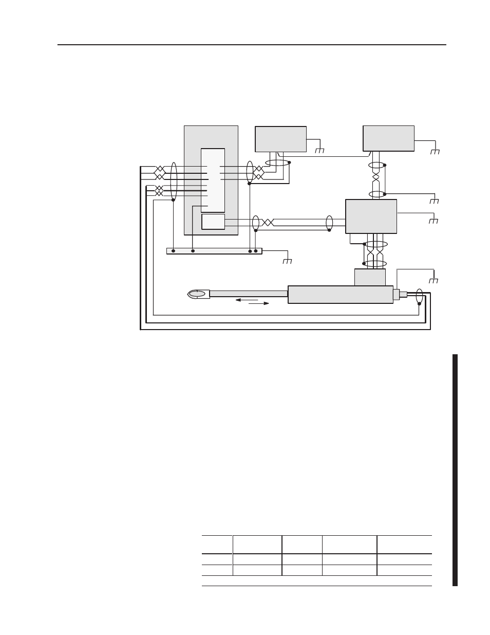
Typical grounding and shielding for this type of control system:
1746-QV
Module
LDT and Hydraulic Ram
Analog Output
Valves
Servo
Proportional
Amplifier
LDT
Signals
24V Power
Supply
"15V Power
Supply
4
earth ground
2
(–) (+)
(+) (C) (–)
Output
Input
Belden
8761
Belden
8761
Case
GND
Case
GND
Case
GND
Cable
Note
Cable
Note
Cable Note: Use cable
recommended by the LDT
and amplifier manufacturer.
Belden
8770
3
1
5-8
LDT
Power
Piston-type Hydraulic Cylinder and
Linear Displacement Transducer (LDT)
0V
Selection of the
"15V Power Supply
The positive and negative supply of some
"15V dc power supplies
decay at different rates when ac power is removed. The module’s
output will be biased, based upon the difference in voltage level
between the positive and negative supply. The duration is dependent
upon the magnitude of the difference and the decay rate. For these
reasons, the
"15V dc power supply should have or be equipped with:
•
proper interlocks with machine operation and e-stop circuits
•
an internal voltage-sense relay that drops the
"15V (without
variation in decay rates) upon loss of ac power
•
auxiliary relay to indicate proper operation and voltage
(such as loss of +15V but not –15 V dc)
Power Supply Loading
The module and LDT load the power supply typically as follows:
Supply
No Transducer
No Load
Transducer
Only *
LDT + Module:
+10V dc @ 10mA
LDT + Module:
–10V dc @ 10mA
+15V dc
86mA
128mA
141mA
128mA
–15V dc
14mA
30mA
30mA
40mA
*MTS Temposonics II, model T1SR0U0120R (Other LDTs will have different loading.)
Considerations for the
"15V dc Supply