Rockwell Automation 1746-QV,D17466.18 OPEN-LOOP VELOCITY CONTL User Manual
Page 13
3–3
Setting Up the Software
Publication 1746-6.18 April 1998
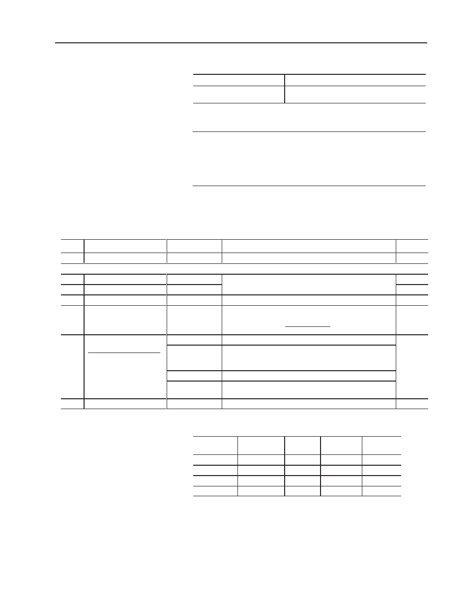
5. Enter values in the G file:
If the module was listed:
If the module was not listed (you entered the ID):
You get the G–file Setup screen.
Enter data from the table, below.
You get the following display, shown in decimal radix.
Enter a value in each word as shown, next.
G–file display for unlisted module (shown in decimal radix):
Ge:0
2056
0
0
0
0
0
0
Enter a value at each G-file word address and press
[ENTER]
.
Then cursor to the next word address and repeat. For example:
Ge:0
2056
893
730
12
1200
–32768
0
We used values from the ladder logic example (appendix B).
You will want to use G-file values that suit your application:
Word:
Function of G-file Word:
Range:
Description of G-file Word or Bit:
Example:
0
Reserved. Do NOT use.
n/a
The processor stores a code for the 1746-QV module.
2056
words 1 & 2 refer to the gradient or transducer calibration value stamped on the name plate on the transducer housing.
1
LDT calibration: upper 3 digits
800-999
ms/inch
For example: To enter an LDT calibration of 8.9373,
u e deci al radi and enter 893 in word 1 and 73 in word 2.
893
2
LDT calibration: lower 3 digits
000-999
ms/inch
For e a ple o enter an
calibration of 8.9373
use decimal radix and enter 893 in word 1 and 730 in word 2.
730
3
Full-scale length (L) of LDT
2
vLv160 inch
Enter the length of the LDT (160 inches max).
12
4
Full-scale count (C)
2
vCvLx100
Typically C = L x 100.
Position Data (I:e.1) = C/(L x 100)
LDT Calibration
1200
5
Configuration Bits
bits 0-12
Set to zero.
–32,768
bit 1 = 1
Configuration Bit
15 14 13 12-0 Equivalent Value
0 1 0 0
+16,384
1 0 0 0
–32,768
1 1 0 0
–16,384
bit 13
0 = output maintained during LDT fault while running profiles and
during SLC mode change
1 = output resets for LDT fault and SLC mode change
–32,768
(bit 15 = 1
for position
increases
towards
head
1 1 0 0
–16,384
0 1 1 0
+24,576
bit 14
Type of LDT: 0 for RPM, 1 for DPM
towards
LDT head)
bit 15
0 = position data increases when moving away from LDT head
1 = position increases when moving toward LDT head
6
Preset Reference
–32,768 to +32,767 Typically zero or home reference value. 32,767 = 327.67 inches.
0
Examples of Full-scale Count Values
LDT Physical
Length
No. of
Recirculations
Resolution
Full-scale
Length (L)
Full-scale
Counts (C)
from 160” to 2”
1
0.01
L (160” to 2”)
L x 100
16”
2
0.01
160
8000
16”
4
0.01
160
4000
16”
10
0.001
160
16000
Important: The module checks for invalid data such as out of
range values or the setting of reserved bits 0-12. You can clear a
data-entry configuration error only by re-entering a corrected value.
6. Save when done
.
Click OK. Click OK. Close window.