Modify n files in your slc processor, off-line, Output image table with profile data, Command and position setpoints for extend #n7:0 – Rockwell Automation 1746-QV,D17466.18 OPEN-LOOP VELOCITY CONTL User Manual
Page 14: Command and position setpoints for retract #n7:20
3–4
Setting Up the Software
Publication 1746-6.18 April 1998
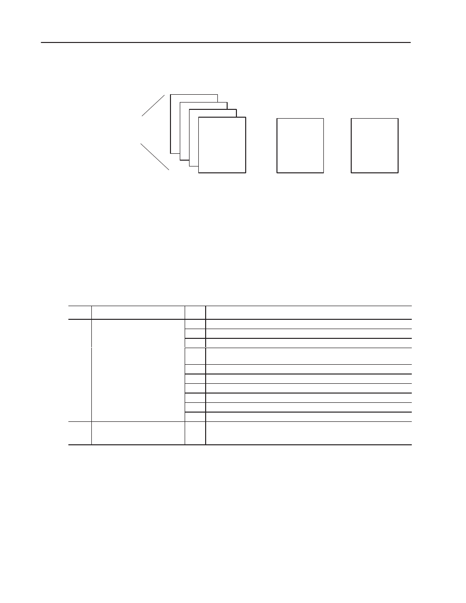
One N file may contain the initial commands, setpoints, and values
for configuring the extend and retract profiles.
Output Image Table
>>>
Command
and
Setpoints
Retract Voltages
Retract Positions
Extend Voltages
Extend Positions
A set of profile data
for initial configuration
Command
and
Setpoints
>>>
>>>
>>>
1746-QV Module
Extend
and Retract
Profiles
>>>
>>>
>>>
>>>
The file contains commands and data starting at the these addresses:
•
command and position setpoints for extend
#N7:0
•
command and voltage (velocity) values for extend #N7:10
•
command and position setpoints for retract
#N7:20
•
command and voltage (velocity) values for retract
#N7:30
The sample ladder program (appendix B) copies profile data into the
output image table from the above locations.
Output Image Table with Profile Data
Word:
Function of Output Image Word:
Bit #:
Description: (For command bits, a 0-to-1 transition enables the command)
0
Command Bits
0
Set to run an extend profile.
Co
and Bit
Enable the e bit
e. /bit
1
Set to run a retract profile.
Enable these bits (O:e.0/bit #)
with our ladder logic where e
2
Set to disable the profile. This bit over-rides bit 0 or 1.
with your ladder logic, where e
represents the I/O slot number.
3
Set to change the current position data to the value of the preset reference
stored in Ge:6.
4
Set to clear any data-entry errors.
5
Set to define words 1-7 as programmed position setpoints for extend.
6
Set to define words 1-7 as programmed voltage values for extend.
7
Set to define words 1-7 as programmed position setpoints for retract.
8
Set to define words 1-7 as programmed voltage values for retract.
9-15
Reserved. Do NOT use.
1-7
Position Setpoint or Voltage Value
n/a
Important: Position setpoints are in units of 0.01” (200 = 2.00”)
within the range of –327.68” to +327.67”, and voltage values in
5mV units (3005 = 3.005V) within the range of
"10,000mV.
The data monitor mode of your programming software displays the
data files shown below (with values from the ladder program).
Important: Modify these values to suit the preset reference chosen
for the G file and/or to match the LDT length.
Extend Positions:
N7:0
32
–45
50
200
300
400
425
500
0
0
Extend Velocities:
N7:10
64
3000
3750
4000
4000
4000
4000
4000
0
0
Retract Positions:
N7:20
128
–45
50
200
300
400
425
500
0
0
Retract Velocities:
N7:30
256
5000
6000
6000
3000
1000
50
25
0
0
Modify N Files in Your
SLC Processor, Off-line