Rockwell Automation 1757-FFLD4 Foundation Fieldbus Linking Device Installation Instructions User Manual
Page 8
8 Foundation Fieldbus Linking Device
Publication
1757-IN021E-EN-P - August 2009
Mount on a DIN Rail
The linking device DIN-rail latch locks in the open position so that the
linking device can be easily attached to or removed from the DIN rail. The
maximum extension of the latch is 15 mm (0.67 in.) in the open position. You
need a screwdriver to remove the linking device. The linking device can be
mounted to 35 x 7.5 or 35 x 15 DIN rails (EN 50 022). See
for
DIN-rail mounting dimensions.
Do these steps to install your linking device on the DIN rail.
1. Verify that the placement of the linking device on the DIN rail allows
for 50 mm (2 in.) of space on all sides for adequate ventilation.
2. Hook the top slot over the DIN rail.
ATTENTION
This product is grounded through the DIN rail to chassis ground. Use zinc
plated yellow-chromate steel DIN rail to assure proper grounding. The use of
other DIN rail materials (for example, aluminum or plastic) that can corrode,
oxidize, or are poor conductors can result in improper or intermittent
grounding. Secure DIN rail to the mounting surface approximately every
200 mm (7.8 in.) and use end-anchors appropriately.
43481
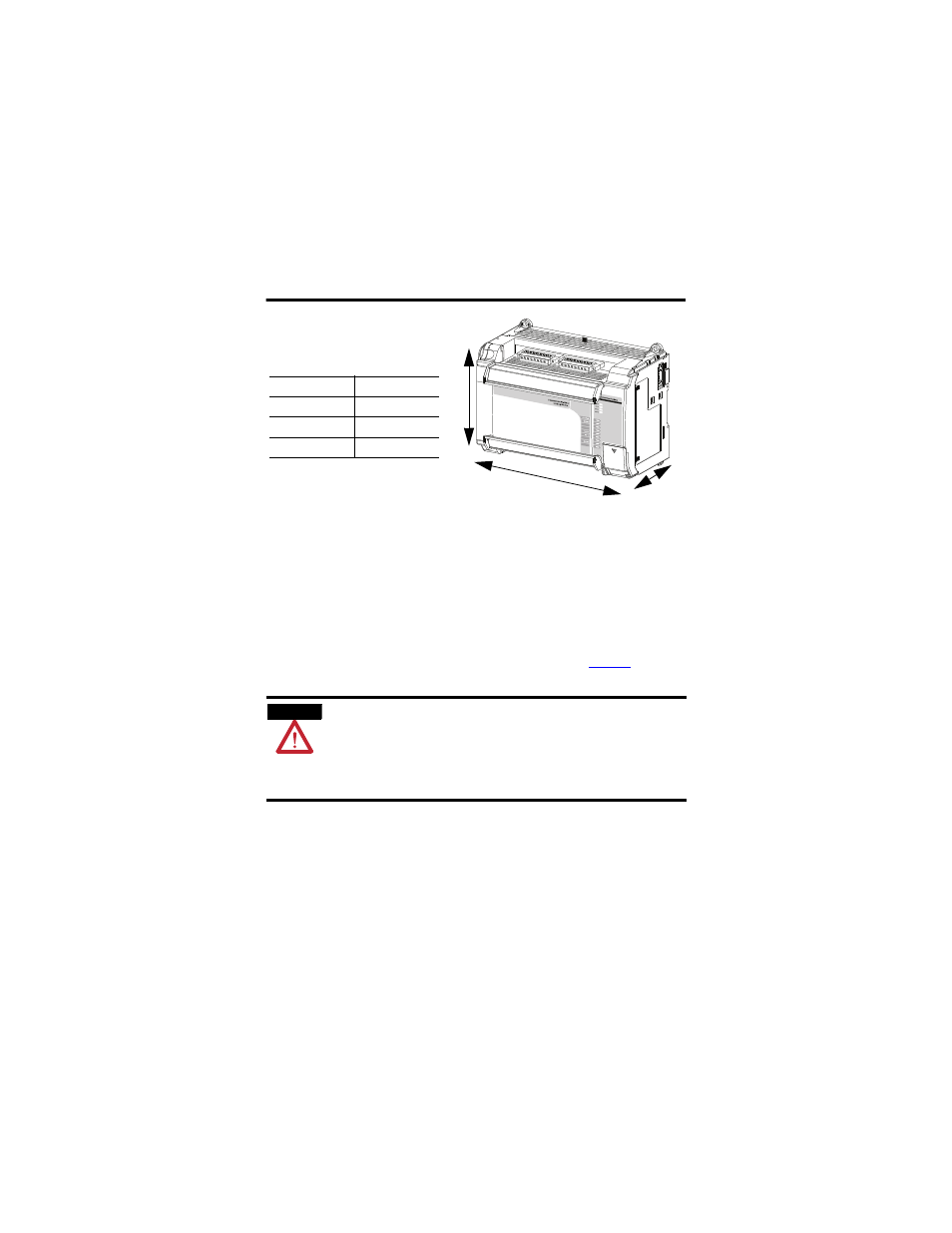
A
B
C
Product Dimensions
Dimension
Measurement
Height (A)
138 mm (5.43 in.)
Width (B)
168 mm (6.62 in.)
Depth (C)
87 mm (3.43 in.)