Ground the controller, Open the access door, Remove and install the sd card – Rockwell Automation 1756-L72EROMS Armor GuardLogix Controller User Manual
Page 8
8 Armor GuardLogix Controller
Rockwell Automation Publication 1756-IN060B-EN-P - November 2013
Ground the Controller
You must provide a proper grounding path by using the ground lug on the bottom of the
enclosure.
Refer to Industrial Automation Wiring and Grounding Guidelines, publication
guidelines on installing an industrial control system.
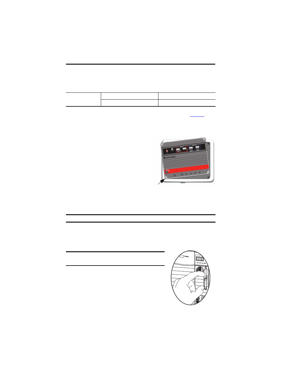
Open the Access Door
Open the enclosure door to access the power switch,
controller USB port, and SD memory card in the
controller.
1. Loosen the four (captive) screws on the front
of the enclosure.
2. Gently lift the door and rotate it counter-
clockwise from the pivot at the lower left
corner.
The door remains attached to the enclosure.
3. Close the access door on the enclosure and torque the four screws to 3.8 N•m
(33.5 lb-in).
Remove and Install the SD Card
If you want to remove the SD card, follow these steps.
1. Open the enclosure door to access the controller.
2. Turn the keyswitch to the PROG position.
3. Press and release the SD card to eject it.
4. Remove the SD card.
5. Close the enclosure access door.
PE Ground
Wire Size
Tightening Torque
1.3…5.2 mm
2
(#16…#10 AWG)
2 N•m (17.7 in-lb)
IMPORTANT
When the access door is open, the Armor GuardLogix controller rating is Type 1.
IMPORTANT
Verify that the SD card status indicator is off and that
the card is not in use before removing it.
TM
®
Armor GuardLogix
24VD
IN
OUT
DC
24VDC
LNK1
LNK2
LNK1
LNK2
Channel A
Channel B
Pull and Rotate
Counter Clockwise
TM
Pivot Point
Logix 55xx
RUN FORCE SD OK