Make power connections – Rockwell Automation 1756-L72EROMS Armor GuardLogix Controller User Manual
Page 11
Armor GuardLogix Controller 11
Rockwell Automation Publication 1756-IN060B-EN-P - November 2013
Make Power Connections
The bottom of the enclosure has two mini-sealed power connectors that operate in parallel with
one another to allow daisy-chaining of device power with other devices. The unit receives its
required power through the male connector. A female connector lets power be daisy-chained to
other Armor GuardLogix units.
1. Remove the dust caps from the power connectors on the bottom of the enclosure.
2. Make power connections and torque to 12 N•m (106 lb-in).
IMPORTANT
Use the 1585D–M4DC–H: Polyamide small body unshielded or the 1585D–M4DC–SH: Zinc
die-cast large body shielded mating connectors for the D-Code M12 female network connector.
IMPORTANT
Use two twisted-pair CAT5E UTP or STP cable.
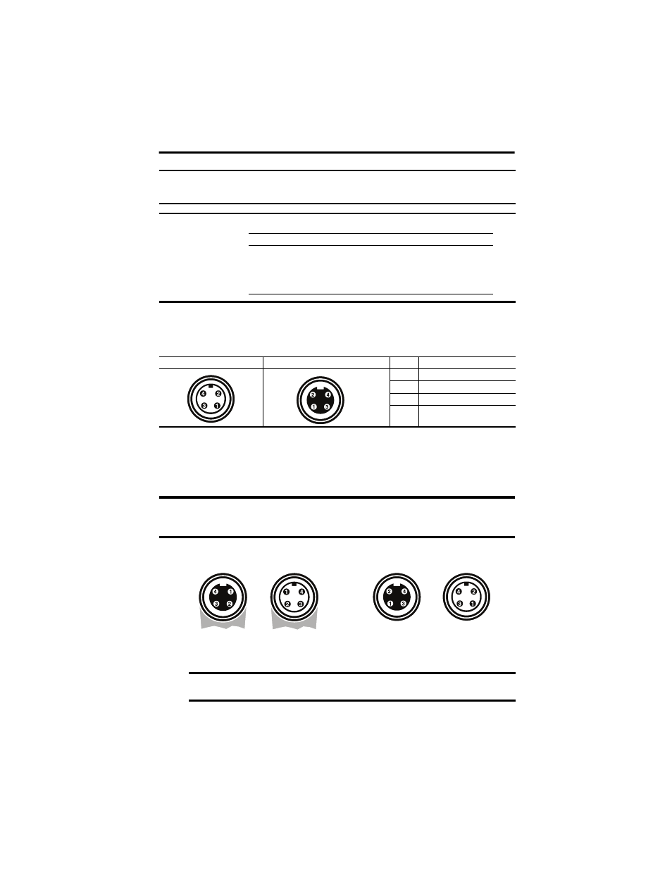
Male Connector (Power Input)
Female Connector (Power Output)
Pin
Signal
1
V+ Switched
2
V+ Unswitched
3
V- Unswitched Common
4
V- Switched Common
IMPORTANT
On Machine end devices, such as the Armor GuardLogix controller, use the EN-50044 wiring
standard while On-Machine cordsets with flying leads use the SAE-J-1738A standard for wiring.
Use care to follow the pin numbering convention shown below before powering up the unit.
IMPORTANT
If you disconnect power connections from these ports, re-attach the dust caps and
torque to 2 N•m (18 lb-in) to maintain IP67 protection.
D-Code M12 Pin
Wire Color
Signal
8-way Modular RJ45 Pin
1
White-Orange
TX+
1
2
White-Green
RX+
3
3
Orange
TX-
2
4
Green
RX-
6
Cordsets with Flying Leads (per SAE-J-1738A)
Armor GuardLogix Controller (per EN 50044)
Female
Female
Male
Male
1-Black [V-] 2-White [E-] 3-Red [V+] 4-Green [E+]
1-Red [V+] 2-Green [E+] 3- White [E-] 4-Black [V-]