Install the armor guardlogix controller, Mount the controller – Rockwell Automation 1756-L72EROMS Armor GuardLogix Controller User Manual
Page 6
6 Armor GuardLogix Controller
Rockwell Automation Publication 1756-IN060B-EN-P - November 2013
Install the Armor GuardLogix Controller
The controller ships with the power switch inside the enclosure set to ON and the controller in
Remote Program mode. You can make power connections and EtherNet/IP network
connections without opening the access door on the enclosure. However, if you need to access
the power switch, USB port, or SD card, you will need to open the enclosure door.
Follow these steps, described in this publication, to install the controller.
1.
2.
3.
, optional
4.
Remove and Install the SD Card
, optional
5.
, optional
6.
7.
8.
Set the Network IP Address of the EtherNet/IP Modules
9.
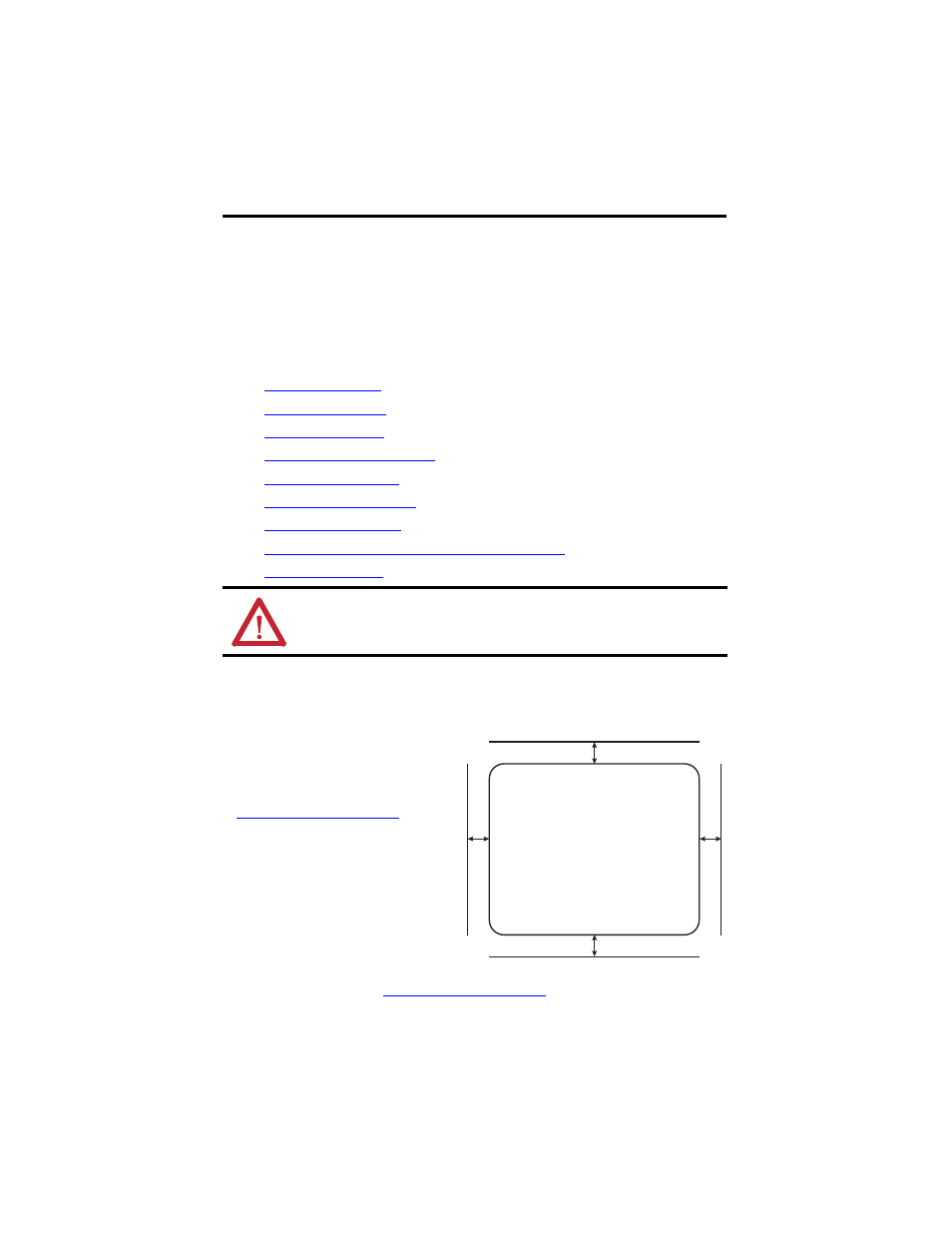
Mount the Controller
Observe these minimum spacing
requirements around the enclosure.
Mounting feet can be attached in either
horizontal or vertical orientation as shown
in
. Attach
the mounting feet to the enclosure by using
the four flat-head screws supplied with the
mounting feet. Torque screws to 8.5 N•m
(75.2 lb-in).
Mount the module directly to a machine by
using four mounting holes. The mounting
hole diameter on the mounting feet
included with the enclosure is 6.8 mm (0.27
in.). Use four M6 screws and torque screws
to 6.6 N•m (58 lb-in). See the
.
ATTENTION: Make sure all connectors and caps are securely tightened to properly seal
connections against leaks and maintain IP67 requirements.
30 mm (1.18 in.)
30 mm (1.18 in.)
30
mm
(1
.18 i
n.)
30 m
m
(1
.1
8 in.)