Interpreting the status indicators on the ktcx15 – Rockwell Automation 1784-KTCX15 INSTL INSTR CONTROLNET COMM. User Manual
Page 9
ControlNet Communication Interface Card
9
Publication 1784-5.33 – September 1997
Selecting the Base I/O Space Address Location
The host addresses I/O devices on the card by using their I/O space address. The
host addresses individual devices through registers that have addresses based on
the I/O space base address. The registers are 2 bytes long.
The card comes set to base I/O space address 220. You may find that this
selected address has been allocated to other interface cards or expansion memory
cards you have installed in your computer system. If this occurs, change the
switch settings to an open address.
Important:
When selecting configuration settings, check for conflicts with
other interface cards and system memory. If there is a conflict, the
system will not operate properly.
To select a new base I/O space address:
1. Pick an available address from the I/O map area of the host computer’s
memory. Be sure to choose a block that is 2 bytes long.
Important:
Each card requires 2 bytes of I/O space.
2. Use Worksheet D to select a new base I/O space address for the card
(i.e., to determine the switch settings for the new address).
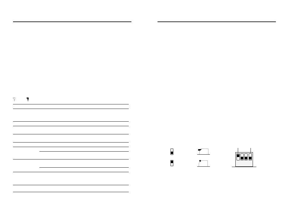
Follow this guide to properly set your switches:
up (1)
down (0)
1 2 3 4
MSB
LSB
Front View
up (1)
down (0)
Side View
Front View
S3
3. Fill in Worksheet E after you’ve determined your switch settings.
4. Follow the instructions that begin on page 11.
28
ControlNet Communication Interface Card
Publication 1784-5.33 – September 1997
Interpreting the Status Indicators on the KTCX15
The status indicators on the card give you information about the card and the
network when you’re connected via the BNC connectors. Table B outlines the
states and explains what each state means to you and the action you should take,
if any, to correct that state.
Table B
ControlNet status interpretation
•
steady –
indicator is on continuously in the defined state.
•
alternating –
the two indicators alternate between the two defined states at the same time (applies to
both indicators viewed together). The two indicators are always in opposite states, out of phase.
•
flashing –
the indicator alternates between the two defined states (applies to each indicator viewed
independent of the other). If both indicators are flashing, they must flash together, in phase.
and
A
B
Cause:
Action:
off
no power
none or power up
steady red
faulted unit
cycle power or reset unit
If fault persists, contact your Rockwell
Automation representative or distributor.
alternating red/green
self-test
none
alternating red/off
incorrect node configuration
check network address and other
ControlNet configuration parameters
off
channel disabled
program network for redundant media,
if required
steady green
normal operation
none
flashing green/off
temporary errors
none; unit will self-correct
node is not configured to go on line
make sure the configuration keeper node
is present and working ➀
flashing red/off
media fault
check media for broken cables, loose
connectors, missing terminators, etc.
no other nodes present on network
add other nodes to the network
flashing red/green
incorrect network configuration
cycle power or reset unit
If fault persists, contact your Rockwell
Automation representative or distributor.
➀ The configuration keeper node is the node responsible for distributing ControlNet configuration data to all nodes on the
network.
Important:
When you have a cable connected to the network access port
(NAP), the LEDs are meaningless.