Apply power to the processor, Ethernet network topology – Rockwell Automation 1747-L55x,D174710.4 SLC 500 Ethernet User Manual
Page 16
2–4
Setting Up the SLC and PC Hardware
Publication 1747-10.4
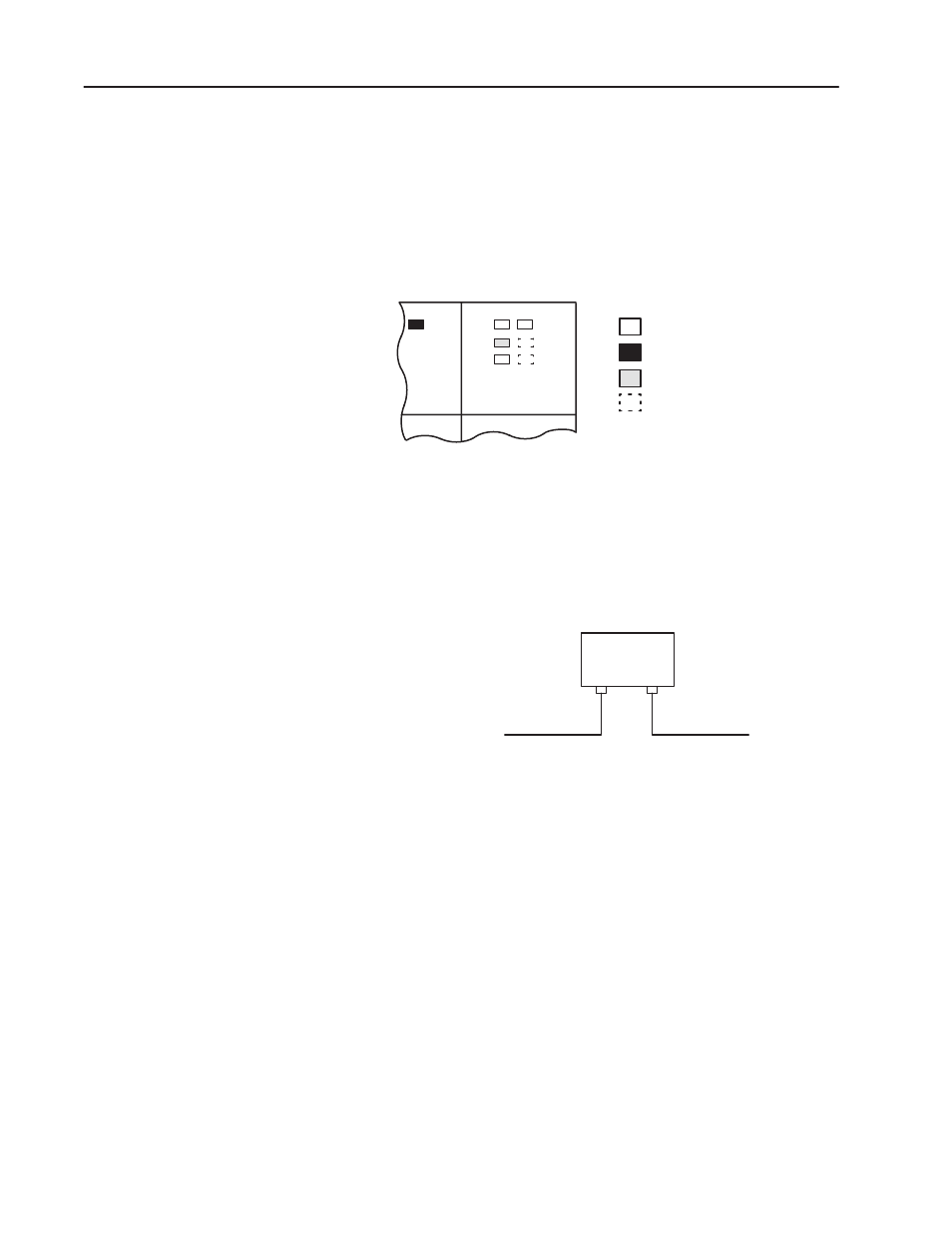
Follow the steps below:
1. Energize the chassis power supply.
2. Check the chassis power supply and processor LEDs. The power
LED on the power supply should be on and the fault LED on the
processor should be flashing.
Indicates the LED is OFF.
Indicates the LED is ON.
Indicates the LED is FLASHING.
Status of LED does not matter.
Power supply and LED Indicators
POWER
RUN
FLT
BATT
FORCE
ENET
RS232
The SLC 5/05 Ethernet connector conforms to ISO/IEC 8802-3 STD
802.3 and utilizes 10Base-T media. Connections are made directly
from the SLC 5/05 to an Ethernet hub. Typical network topology is
pictured below.
Ethernet Network Topology
to SLC 5/05
Channel 1
to PC Ethernet Card
RJ45 connectors
on both ends of cable
(10Base-T)
Ethernet
Hub
Important:
The SLC 5/05 processor contains a 10Base-T, RJ45
Ethernet connector which connects to standard Ethernet
hubs via 8-wire phone jack cable. To access other
Ethernet mediums, use Ethernet hubs that can be
connected together via fiber, thin-wire, or thick-wire
coaxial cables, or any other physical media
commercially available with Ethernet hubs. In addition,
media converters are commercially available to convert
10Base-T to other Ethernet media.
Apply Power to the
Processor
Connect the SLC 5/05 and
the PC to the Ethernet
Network