Dip switch sw1 – Rockwell Automation 1503 IntelliVAC Contactor Control Module - Series C and later User Manual
Page 38
Setup and Commissioning
4-3
1503-UM051C-EN-P – June 2005
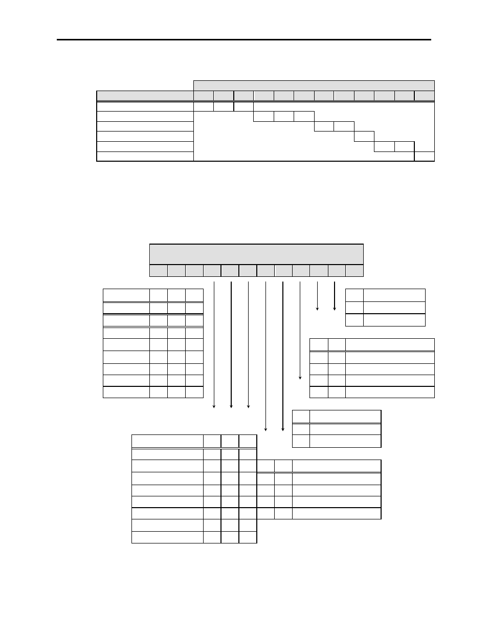
Table 4.A – DIP Switch Factory Default Settings
DIP switch
Description
1
2
3
4
5
6
7
8
9
10
11
12
Altitude: 0 – 1000m
0
0
1
Drop-out time: 130 msec
0
1
1
Contactor config.: 400A EH
0
1
TDUV config.: No TDUV
0
Ext. cap TDUV time: 0.2 sec
0
0
Power-Up Safety: Enable
0
IntelliVAC units shipped in a complete MV controller (Bulletin
1500/1900) will be configured to suit the installed application (i.e.
contactor type). The user should verify the settings before energizing the
equipment. Table 4.B defines the settings for each switch.
Table 4.B – IntelliVAC DIP Switch Explanation
UP = 1
DOWN = 0
DIP switch SW1
1
2
3
4
5
6
7
8
9
10 11 12
|
|
|
|
Altitude
1
2
3
12
Power-Up Safety
-1000 to 0
0
0
0
0
Enable
1 to 1000
0
0
1
1
Disable
1001 to 2000
0
1
0
2001 to 3000
0
1
1
10
11
Ext. cap. TDUV time
3001 to 4000
1
0
0
0
0
0.2 sec
4001 to 5000
1
0
1
0
1
0.5 sec
Not defined
1
1
0
1
0
1.0 sec
Not defined
1
1
1
1
1
2.0 sec
9
TDUV config.
0
No TDUV
Drop out time
4
5
6
1
TDUV Enabled
50 msec
0
0
0
75 msec
0
0
1
7
8
Contactor Config.
100 msec
0
1
0
0
0
400A Mech. Latch
130 msec
0
1
1
0
1
400A Elec. Held
150 msec
1
0
0
1
0
800A Mech. Latch
175 msec
1
0
1
1
1
800A Elec. Held
200 msec
1
1
0
240 msec
1
1
1
The altitude compensation by DIP switch settings applies to Series E 400 amp vacuum contactors only. All 800 amp contactors are adapted
for altitude by altering the return springs. 800 amp contactors are to be set for 1 to 1000m (001 DIP setting).