Wiring – Rockwell Automation 1403-NSC Smart Communication Card Instruction Sheet User Manual
Page 4
Smart Communications Card
4
Publication 1403-5.1
Wiring
!
ATTENTION: Special high level
isolation is required between units when
the possibility of high ground potential
differences exist. This may occur when
separate grounds are used or when
communicating to a unit connected to a
power ground mat. Failure to do so can
lead to personal injury or death, property
damage, or economic loss.
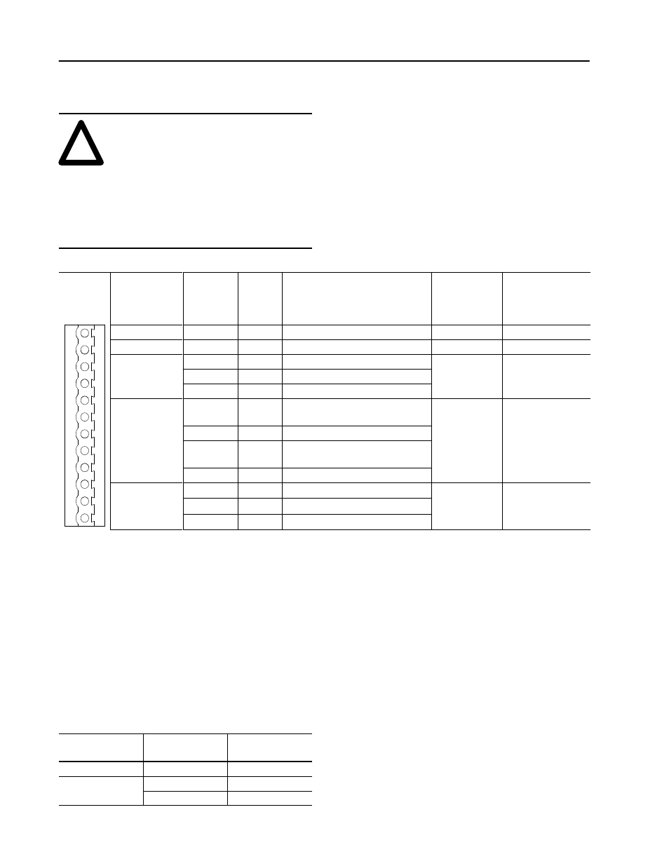
Table A. Wiring Connections
Connector
Communication
Format
Terminal #
(Counting
from the
bottom up)
Terminal
Label
Intended Use, Pin Connection,
or Wire Color
Recommended
Cable Type
Maximum Cable
Length/Baud Rate
12
Do not connect
11
Do not connect
10
SHLD
Cable shield grounding point
2 ire shielded
RS-485
9
–
Minus signal data
2-wire shielded
(Belden 9841)
4000 ft/19.2kB
RS 485
8
+
Plus signal data
(Belden 9841)
4000 ft/19.2kB
7
RXD
PC Transmit, DB25, pin 2,
(DB9, pin 3)
RS-232
6
TXD
PC Receive, DB25, pin3 (DB9, pin 2)
3-wire Shielded
50 ft/19 2kB
RS-232
5
SG
PC signal return, DB25, pin 7
(DB9, pin 5)
3-wire Shielded
(Belden 9608)
50 ft/19.2kB
4
SHLD
Cable Shield
3
1
Blue Wire insulation
1770-CD
T i
i l
10,000 ft /57.6kBaud
R-I/O
2
SHLD
Cable shield ground point
1770 CD
Twinaxial
(Blue Hose)
10,000 ft /57.6kBaud
5,000 ft/115.2kBaud
2 500 ft/230 4kB d
R I/O
1
2
Clear wire insulation
(Blue Hose)
(Belden 9463)
5,000 ft/115.2kBaud
2,500 ft/230.4kBaud
Notes:
1. The communications topology for both R I/O and
RS-485 is designed to operate in a daisy-chain
topology. Use of the star or bridging method will
cause signal distortion unless impedances are
matched for each spur. Bridging is not recommended
without matching networks.
2. To prevent end reflections, each end of the daisy-
chain should be terminated in the characteristic
impedance for the cable, the baud rate, and frequency
used.
Communication
Format
Baud Rate
Terminating
Resistor
RS-485
1200–19.2k
150
Ω
1/4 W
R I/O
57.6–115.2k
150
Ω
1/4 W
R I/O
230.4k
84
Ω
1/4 W
3. Each end section of cable should have the shield
connected to the terminal labeled SHLD. This SHLD
ground provides a high frequency ground, while
limiting DC or power line frequencies from flowing
down the cable shield.
4. The RS-485 receivers in the communications card
provide a 1/4 load impedance instead of the normal
full load impedance. This therefore allows the use of
four times the number of receivers (32
4 or 128
total) on one network.