Rockwell Automation 1403-NSC Smart Communication Card Instruction Sheet User Manual
Rockwell Automation Equipment
Publication 1403-5.1
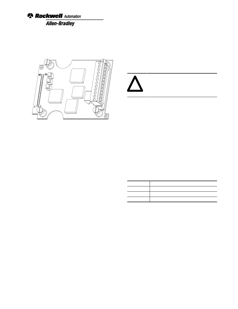
Smart Communications Card
(Cat. No. 1403-NSC)
Important User Information
Solid-state equipment has operational characteristics
differing from those of electromechanical equipment.
Safety Guidelines for the Application, Installation, and
Maintenance of Solid-state Controllers (Publication
SGI-1.1) describes some important differences between
solid-state equipment and hard-wired electromechanical
devices. Because of this difference, and also because of
the wide variety of uses for solid-state equipment, all
persons responsible for applying this equipment must
satisfy themselves that each intended application of this
equipment is acceptable.
In no event will the Allen-Bradley Company, Inc. be
responsible for indirect or consequential damages
resulting from the use or application of this equipment.
The examples and diagrams in this manual are included
solely for illustrative purposes. Because of the many
variables and requirements associated with any particular
installation, the Allen-Bradley Company, Inc. cannot
assume responsibility or liability for actual use based on
the examples and diagrams.
No patent liability is assumed by the Allen-Bradley
Company, Inc. with respect to use of information,
circuits, equipment, or software described in this manual.
Reproduction of the contents of this manual, in whole or
in part, without written permission of Allen-Bradley
Company, Inc., is prohibited.
Throughout this manual we use notes to make you aware
of safety considerations:
!
ATTENTION:
Identifies information
about practices or circumstances that can
lead to personal injury or death, property
damage or economic loss.
Attention statements help you to:
•
identify a hazard
•
avoid the hazard
•
recognize the consequences
Important:
Identifies information that is critical for
successful application and understanding
of the product.
Terms and Conventions
In this instruction sheet, the following terms and
conventions are used:
Abbreviation
Term
BTR
Block Transfer Read
BTW
Block Transfer Write
MSG
Message
Table of Contents
Product Description
2
. . . . . . . . . . . . . . . . . . . . .
Installation
3
. . . . . . . . . . . . . . . . . . . . . . . . . . .
General Operation
8
. . . . . . . . . . . . . . . . . . . . . .
Catalog Number Explanation
App. A
. . . . . . . . . . . . . .
Smart Communication Card Data Tables
App. B
. . . . . .
Smart Communication Protocol Tutorial
App. C
. . . . . . .
Sample Ladder Listing
App. D
. . . . . . . . . . . . . . . . . . .
Technical Specifications
App. E
. . . . . . . . . . . . . . . . . .
PLC is a registered trademark of Allen-Bradley Company, Inc.
Data Highway Plus and SLC are trademarks of Allen-Bradley Company, Inc.
Instruction Sheet
Document Outline
- 1403-5.1, Smart Communications Card Instruction Sheet
- Important User Information
- Terms and Conventions
- Product Description
- Installation
- General Operation
- A - Catalog Number Explanation
- B - Smart Communication Card Data Tables
- Table B.1 Data Table List
- Table B.2 Device Configuration Data Table - Write and Read
- Table B.3 Smart Communication Card Data Table – Write and Read
- Table B.4 Command Data Table Write
- Table B.5 Bit Fields for Command Data Table (Command Word 1)
- Table B.6 Bit fields for Command Data Table (Command Word 2)
- Table B.7 Voltage/Current Data - Read
- Table B.8 Real Time Power Data - Read
- Table B.9 Cumulative Power Data - Read
- Table B.10 Demand Data - Read
- Table B.11 Event Log - Read
- Table B.12 Voltage/Current/Miscellaneous Snapshot Log Data Table Read
- Table B.13 Power Snapshot Log Data Table
- Table B.14 Min_Max Log - Read
- Table B.15 Log Selection Command Table Write
- Table B.16 Available Min/Max Log Parameters (Identifiers for parameter 12.4)
- Harmonic Distortion Tables - Read
- Table B.17 Even Harmonic Distortion Table - Channel 1
- Table B.18 Odd Harmonic Distortion Table - Channel 1
- Table B.19 Even Harmonic Magnitude Data Table Channel 1
- Table B.20 Odd Harmonic Magnitude Data Table
- Table B.21 Even Harmonic Phase Angle Data Table Channel 1
- Table B.22 Odd Harmonic Phase Angle Data Table
- Table B.23 Oscillogram Capture Data - Read
- Table B.24 Diagnostic Data Table (Self-test Results) Read
- Table B.25 Setpoint Setup Data Table - Write/Read
- Table B.26 Setpoint Type
- Table B.27 Setpoint Action
- Table B.28 Relay/Setpoint Status Table Read
- Table B.29 Status Inputs Bitfield Definitions
- Table B.30 Alarm word Bitfield Definitions
- Table B.31 Setpoint Status Bitfield Definitions
- C - Serial Communication Protocol Tutorial
- D - Sample Ladder Listing
- E - Technical Specifications
- Back Cover