Rockwell Automation 1394-DIM Installing Your Drive Interface Module User Manual
Page 3
Installing Your 1394 Drive Interface Module
3
Publication 1394-5.12 December 1999
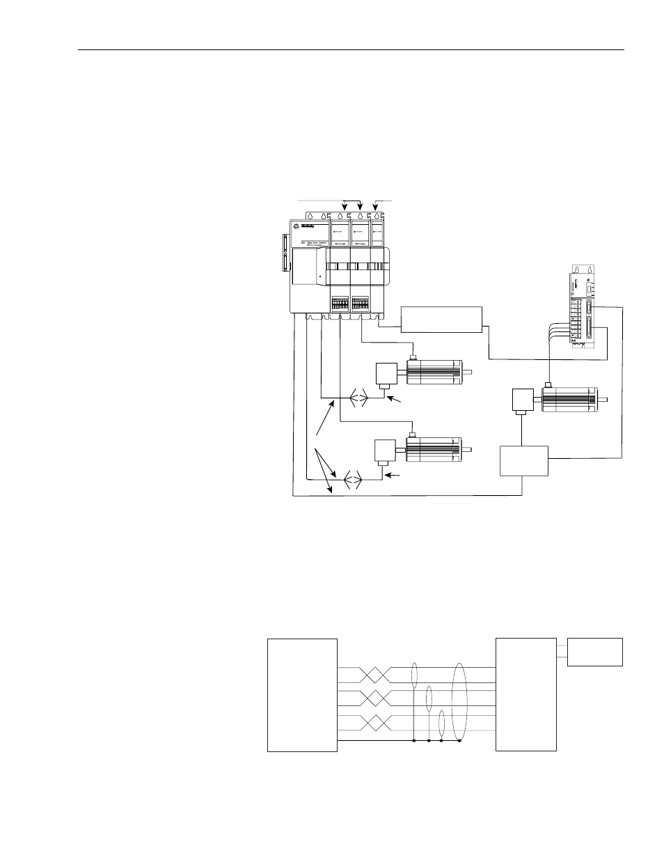
In the figure below, the 1394-DIM is connected to a 1394 GMC Turbo
with two 1394 axis modules and a 1398-DDM-xxx servo controller. A
1326AB-Bxxxx motor is directly connected to each of the 1394 axis
modules. One servo amplifier with motor is connected to the
1394-DIM.
Figure 3
1394-DIM Connected to a 1398-DDM-xxx
Figure 4 shows the J1 breakout board interconnect details between the
1394-DIM and the 1398-DDM-xxx. Refer to ULTRA 200 User
Manual (publication 1398-5.0) and ULTRA 100 User Manual
(publication 1398-5.2) for more information.
Figure 4
1394-DIM to J1 Breakout Board Pinouts
! ?
J5
J2
J1
TB1
1394 GMC or GMC
Turbo System Module
Status
Encoder
1326AB
1394 Axis Modules
1394-DIM
Encoder
H, F, Y, or N
Series Motor
1394-GE15
9101-1392
Axis 1
Axis 0
1398-DDM-xxx
J1
J2
Motor
Power
J2 Breakout
Board
1326AB
Encoder
J1 Breakout Board
(Refer to Figure 4)
9101-1391
Axis 2
1326-CEU-xxx
(If A-B 845H)
1326-CEU-xxx
(If A-B 845H)
24V I/O
Power Supply
1
1394-DIM Cable Connector
Belden 8163
cable or equivalent
J1 Breakout Board
1
Required on ULTRA 100 only
2
x = axis controlled by DIM
2
+ Analog Out Px-1
– Analog Out Px-2
– Drive Enable Px-3
+ Drive Enable Px-4
+ DROK Px-5
– DROK Px-6
Shield Px-7
J1-22 CMND +
J1-23 CMND -
J1-20 Enable
J1-26 I/O PWR
J1-25 Ready -
J1-24 Ready +
J1-5
J1-6