Rockwell Automation 1394-DIM Installing Your Drive Interface Module User Manual
Page 13
Installing Your 1394 Drive Interface Module
13
Publication 1394-5.12 December 1999
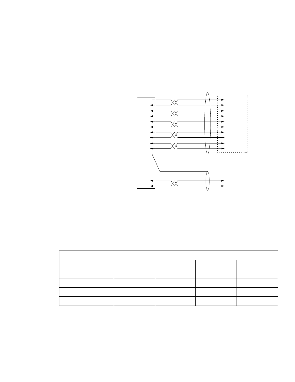
Connecting the Position Feedback Encoder to the Feedback Input
The figure below shows the pinouts and interconnect information for
the auxiliary encoder input to the 1394-GMC.
Figure 19
1394-GE15 Cable Connections
1
Customer supplied 5V DC power source is required for encoder board whether encoder supply voltage is
5V or not.
To connect the encoder feedback cable to the 1394 system module:
1. Plug the 1394-GE15 cable for each DIM Axis into the correct
auxiliary encoder input on the 1394 system module as shown in
the table below. Refer to Figures 9, 10, and 11 for encoder input
locations.
Note:
The other end of the 1394-GE15 cable provides flying
leads and must be connected to correct signals on a
quadrature encoder.
Note:
The feedback inputs for axis 0, 1, 2 and 3 (on 1394x-SJTxx-
C and -T systems) and for axis 0 and 1 (on 1394x-SJTxx-
L systems) run from front to back (see Figure 20).
7
1
2
3
4
5
6
8
9
12
10
11
Black
Yellow
White
Black
Green
Black
Blue
Black
Red
Black
Shield
NC
Strobe
A High
A Low
B High
B Low
Z High
Z Low
+5V Out
Common Out
1394 Encoder
Feedback Connector
Flying Leads to
Incremental Encoder or
Customer-Supplied Termination
NC
Shield
Red
Black
+5V Input
Common In
Encoder Power
(ENC. PWR)
Cable is Belden 9505
Cable is Belden 9501
1
When this axis is used:
Install the Position Feedback Input plug for:
DIM axis A into: DIM axis B into: DIM axis C into: DIM axis D into:
0 (no axis installed)
J3
J4
J5
J10
1 (axis 0 installed)
J4
J5
J10
N/A
2 (axis 0, 1 installed)
J5
J10
N/A
N/A
3 (axis 0, 1, 2 installed) J10
N/A
N/A
N/A