Connecting the remote drive to the dim connector – Rockwell Automation 1394-DIM Installing Your Drive Interface Module User Manual
Page 10
10
Installing Your 1394 Drive Interface Module
Publication 1394-5.12 December 1999
Wiring and Configuring an External
Drive to the 1394-DIM
This section includes the following steps for wiring and configuring
an external drive to the 1394-DIM:
•
Connecting the remote drive to the DIM connector that provides
the
]10V output, the drive enable output, and the drive status
input.
•
Connecting the position feedback encoder to the auxiliary
feedback input on the 1394 GMC/GMC Turbo system module.
This provides position information for closing the position and
velocity loop for the drive.
•
Connecting the DIM ground wire to the 1394 system module.
•
Installing the resolver feedback input plug for each DIM axis to
prevent resolver loss faults.
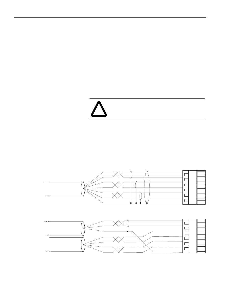
Connecting the Remote Drive to the DIM Connector
The customer supplied DIM cable leads require terminating at the
DIM cable connector. Follow one of the example configurations, as
shown in the figure below.
Figure 16
DIM Connector Wiring Examples
!
ATTENTION: To avoid personal injury as a result of
unexpected motion or acceleration of the drive, insert
the resolver plug in the correct location.
Belden 8163
or equivalent
DIM cable connector
DIM cable connector
17
17
+ Analog Out Px-1
– Analog Out Px-2
– Drive Enable Px-3
+ Drive Enable Px-4
+ DROK Px-5
– DROK Px-6
Shield Px-7
+ Analog Out Px-1
– Analog Out Px-2
– Drive Enable Px-3
+ Drive Enable Px-4
+ DROK Px-5
– DROK Px-6
Shield Px-7