Dimensions, 1394-dim system examples, The 1394-dim dimensions are shown below – Rockwell Automation 1394-DIM Installing Your Drive Interface Module User Manual
Page 2
2
Installing Your 1394 Drive Interface Module
Publication 1394-5.12 December 1999
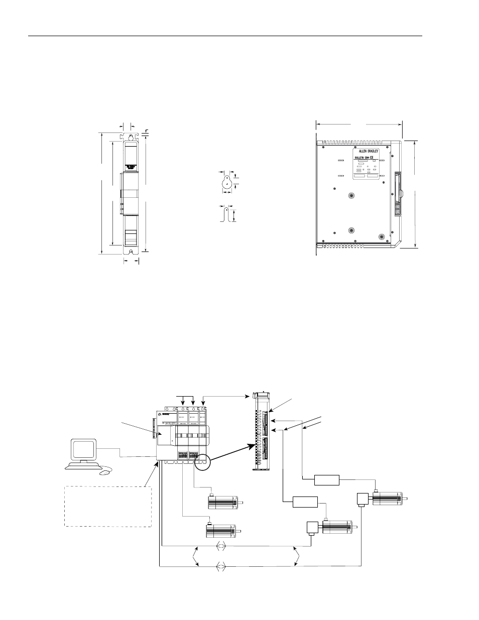
Dimensions
The 1394-DIM dimensions are shown below.
Figure 1
1394-DIM Dimensions
1394-DIM System Examples
In the figure below, the 1394-DIM is connected to a 1394 GMC Turbo
with two 1394 axis modules. A 1326AB-Bxxxx motor is directly
connected to each of the 1394 axis modules. Two servo amplifiers
with motors are connected to the 1394-DIM. It can accept two
because there are two axis modules connected to the 1394 GMC
Turbo. The encoders attached to the motors have encoder feedback
cables connected to the system module.
Figure 2
1394-DIM Connected to a GMC or GMC Turbo
350.0
(13.78)
400.0
(15.75)
50.0
(1.97)
25.0
(0.98)
Dimensions are in millimeters and (inches)
385.0 (fastener location)
1
(15.16)
8.0 (0.32)
All slots accept M6 or 1/4-20 mtg. screws
Mounting Hole Detail
12.0 (0.47)
8.0 (0.31)
8.0 (0.31)
10.1 (0.40)
15.9 (0.63)
1 Dimension shown is for mounting hardware
location and does not reflect the location
of the lower slot radius.
280
(11.02)
350
(13.78)
GML
1326AB
RS-232/-422
1394 GMC or GMC
Turbo System Module
Status
Encoder
Servo Amplifier
Servo Amplifier
1326AB
1394 Axis Modules
1394-DIM
Encoder
Motor
Motor
1394-GE15
Encoder Feedback Cable
Encoder Feedback Cable
Axis 1
Axis 0
1326-CEU-xxx
(if A-B 845H)
1394-DIM ground connector
See Figure 19 for Auxiliary Encoder
input pin-outs and Figure 20 to view
the Auxiliary Encoder Connectors on
a bottom view of the 1394 GMC/GMC
Turbo system module.
DIM A axis connector
DIM B axis connector
+/- 10V reference
Drive Enable
Drive OK (see Figure 16)
Axis connections
located on the
underside of DIM