Rockwell Automation 1395 Discrete Adapter, Rev 3.XX-8.XX User Manual
Page 30
Chapter 5
StartĆUp
5-7
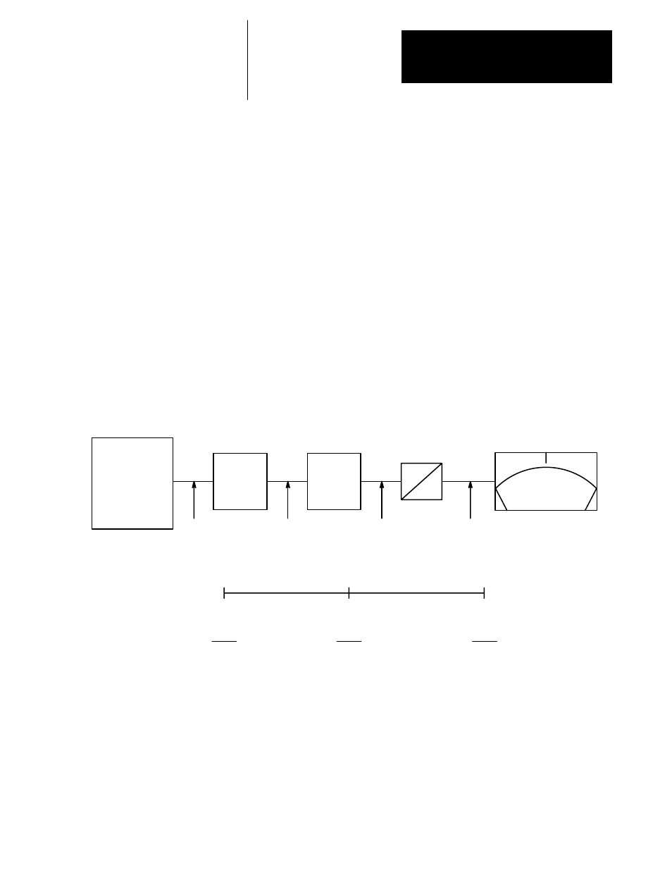
Analog Output 1 and Analog Output 2 will be used as examples in
detailing the scaling and offset parameters. At Analog Output 1, a meter
with a range of 0 to 10 V DC has been connected. Parameter 451 has been
linked to Parameter 106, Velocity Feedback. In order for the meter to
indicate speed in both directions, the scale and offset parameters must be
adjusted (see Figure 5.4). Working in the opposite direction as the analog
inputs, apply the scaling factor first. The drive will send a
±
4096 digital
value to indicate
±
100% velocity feedback, for a total digital range of
8192. The meter, having an analog range of 0 to 10V DC, requires a digital
range of 2048. By applying a scale factor of 0.25 this is accomplished
(8192 x 0.25 = 2048). In order to have the 0 to 10V DC meter indicate
±
100% feedback, an offset must be applied. Offset parameters for analog
outputs will again add the corresponding digital value to the range. In this
case, an offset of 5 volts adds a digital value of 1024 to the range. This will
allow full range deflection on the 0 to 10 volt meter, with 5 volts indicating
zero speed.
Figure 5.4
Example 1: Analog Output
+/- 100% Speed Indication
Scale
0
Digital Range
0.25
-100%
B. Spd.
0 Spd.
+100%
B. Spd.
5V
0V
10V
Offset
5v
+4096
0
-4096
+1024
0
-1024
+2048
+1024
0
+10V = + 100% Base Speed
+5V = 0 Speed
0V +/- 100% Base Speed
-4096
4096
-1024
+1024
0
0 Volts
-100%
0
+1024
1024
5 Volts
0%
+1024
+1024
2048
10 Volts
+100%
from Drive
Scale by 0.25
Offset by 5V,
Adding 1024
Digital Value
Meter Voltage
% Base Spd.
A
D
4096 = 100%
or 1 per unit
Example 1:
±
100% B. Speed
-4096 to +4096