Rockwell Automation 1395 Discrete Adapter, Rev 3.XX-8.XX User Manual
Page 29
Chapter 5
StartĆUp
5-6
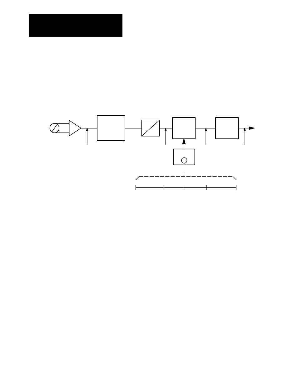
As seen in Figure 5.3, the offset voltage adds the corresponding digital
value to the range. In this case, an offset of –5 volts adds a digital value of
–1024 to the range. This causes 0 volts on the potentiometer to register as
–1024 digital internal to the Drive. This can then be scaled so that 0 volts
sends a digital value of –4096 for –100% Torque.
Figure 5.3
Example: Potentiometer 0 to 10V Range to Control
±
100% to
±
100% Torque Reference
-4096
+4096
0 to 10V
Pot
+0V
to
10V
Multiplexer
A
D
+/- 2048
Scale
X4
To P402
+0
-1024
+1024
Offset
P551 = -5V
Range of 20V
0V
0
0
5V
1024
Potentiometer
Digital Value
Offset by -5V
to
2048
5V = 100% T
Offset
+ 1024
X4
4096
-10V
10V
0
0
+10V
+2048
+1024
+4096
-1024
-4096
Adding -1024
Scale by 4
Analog outputs are set up similar to analog inputs. Each output has a scale
and offset parameter, along with a specific variable parameter used for
linking. Differences occur because of the direction of information flow.
The drive sends a digital value in drive units, which must be matched to the
voltage of the monitoring device. As in the analog inputs, the analog output
converts a
±
2048 to
±
10V DC. Thus, when the drive sends
±
100% Base
Speed (equal to
±
4096) it must be scaled by 0.5 to be in the proper range
(4096 x 0.5 = 2048). Offset can be
±
20V DC, even though the physical
limit is
±
10V DC. This allows you to offset the signal anywhere within the
entire range.