Remove power from all equipment, Left-side kits, Right-side kits – Rockwell Automation 21G PowerFlex 755 Transition Section and Splicing Kit User Manual
Page 3: Powerflex 755 drive
Rockwell Automation Publication 750-IN027C-EN-P - November 2013
3
PowerFlex 755 Transition Section and Splicing Kit for Floor-mount Drives and CENTERLINE 2100 Motor Control Centers
Left-side Kits
Follow all steps including the
Left-side Kit Assembly
sequence for 20 in. deep
left-side-mount transition sections and the 15 in. deep left- or right-side-mount
transition section.
Right-side Kits
Follow all steps including
Right-side Kit Assembly
sequence for 20 in. deep right-
side-mount transition sections and the 15 in. deep left- or right-side-mount
transition section.
Remove Power from All
Equipment
Remove power from all equipment before proceeding with these instructions.
Refer to the product’s installation instructions and review all safety precautions
before performing work on this equipment.
PowerFlex 755 Drive
1.
Turn off and lock out all input power, including any and all external power
sources.
2.
Wait 15 minutes and verify that there is no voltage at the drive’s input
power terminals.
3.
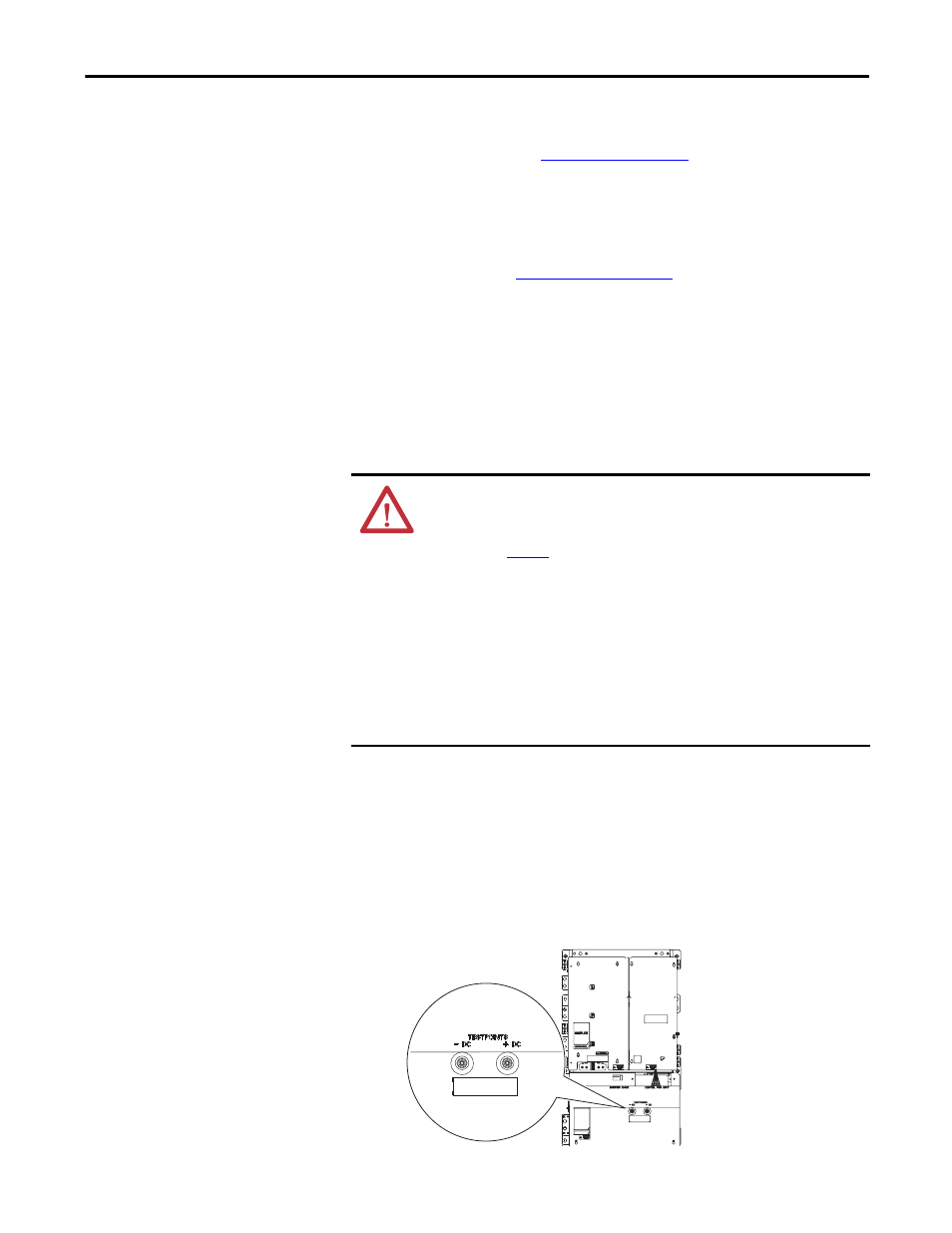
Measure the DC bus voltage at the -DC and +DC TESTPOINT sockets
on the front of the power module.
Figure 1 - PowerFlex Drive -DC and +DC Testpoint Sockets
ATTENTION: To avoid an electric shock hazard, verify that the voltage on the
bus capacitors has discharged completely before servicing. Measure the DC bus
voltage at the -DC and +DC TESTPOINT sockets on the front of the power
module (see
Figure 1
for location).
Remove power before making or breaking cable connections. When you remove or
insert a cable connector with power applied, an electrical arc may occur. An
electrical arc can cause personal injury or property damage by:
• sending an erroneous signal to your system’s field devices, causing unintended
machine motion
• causing an explosion in a hazardous environment
Electrical arcing causes excessive wear to contacts on both the module and its
mating connector. Worn contacts may create electrical resistance.
Frame 8 AC Input Drive Shown