Original instructions, Installation, Mounting of the muting controller box – Rockwell Automation 445L Installation and Operating Instructions User Manual
Page 18
R
Muting Controller Box Installation and Operating Instructions
18
Original instructions
Muting System Examples (continued)
Installation
If mounting the Rockwell Automation Guardmaster muting box as a standalone muting box, it is best to locate this muting box adjacent
to the muting sensors and safety light curtain. The enclosure may be mounted to a smooth flat surface by using the brackets supplied
with the muting box.
It is also possible to mount the enclosure to the Rockwell Automation floor mounting stand (445L-AMSTD2M). This two meter stand kit
comes with a aluminum floor plate, hardware, and Installation instructions. Depending upon the muting system design, it may be
necessary to purchase one or two 500 mm aluminum post kits (445L-AMSTDMUT) that are designed to be cantilevered from the side of
the vertically mounted floor stand.
Mounting hardware (T-nuts, and screws) are included in the two meter stand and 500 mm post kits to mount the muting sensor, light
curtain and muting box
1
.
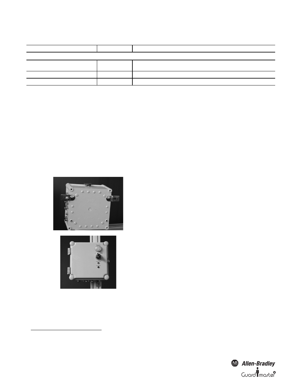
Mounting of the Muting Controller Box
Product
Part Number
Description
If external mute lamp is desired, one mute lamp option with right angle bracket is below
Muting lamp with bracket
1x
855E-24TL7
855E-BVMC
Muting lamp with right angle bracket
Muting lamp patchcord
1x
889P-M4AB-5
4 conductor M8 Pico patchcord, 5 meters
Optical interface
1x
445L-AF6150
Optical interface (can be reused for further configuration)
1.
T-nuts and screws for:
Safety light curtain Safe4, Safe2, 445L-AF6145 for Micro 400, GuardShield 440L,
Muting sensor bracket 60-2649 (RightSight) and 92-39 Reflector
Muting box
Mount the brackets on the muting box.
Tighten the screws properly.
Determine where on the mounting stand the muting box will be
located.
Check for height position with respect to the cable wiring of the
light curtain, muting sensors and muting lamp.
Connectors should be positioned on the bottom side of the muting
box.
Premount the muting box with the T-slot nuts to the mounting
column.
Do not tighten the screws until the box is in right position.
Tighten the screws alternately.