Original instructions, Installation and alignment procedure – Rockwell Automation 445L GuardShield Micro 400 Safety Light Curtain User Manual User Manual
Page 13
R
GuardShield™ Micro 400 Safety Light Curtain User Manual
11
Original instructions
The GuardShield Micro 400 must be mounted at the proper
distance from the point of operation hazard. This distance is
referred to as the Safety Distance.
Figure 7: Determining machine stopping time and safety distance
Installation and Alignment Procedure
Standard GuardShield Micro 400
The alignment procedure can be made easier with the use of integrated
indicator LEDs (Table 1).
1. Mount the transmitter and receiver with the brackets (Figure 9). Make
sure that the longitudinal axis of both are oriented parallel to each other.
For a vertical or horizontal mounting a level might help to find the
correct position.
2. Take care that the receiver and transmitter are oriented in the
same direction. This means, the beginning of the protective field
which is found next to the cable which leads to the safety
controller, must be located at the same end of the protective
field. A reference would be that the indicator LEDs are opposite
one another. It is not allowed to mount the GuardShield Micro
400 systems rotated 180° (Figure 8: Layout of the transmitter/
receiver).
3. Connect the transmitter and receiver to the controller and
power up according the description in the following section.
The indicators will help for alignment.
4. After aligning the longitudinal axis of the transmitter and
receiver, rotate the receiver along the longitudinal axis to find
the receiving angle. During rotation, the receiving angle is
shown by the illumination of the green LED in the GuardShield
Micro 400 light curtain. If this green LED is blinking, the amount
of light detected by the receiver is not sufficient for stable
operation. After realigning the light curtain, the protective field
must be briefly interrupted. After removing the object from the
protective field, a sufficient intensity level is indicated by the
illumination of the green LED in the light curtain.
5. Adjust and mount the receiver at the center of this operating
angle.
6. After aligning the receiver, rotate the transmitter to find the
transmitting angle. During rotation, the transmitting angle is
shown by the illumination of the green LED in the GuardShield
Micro 400 light curtain.
7. Adjust and mount the transmitter at the center of this
operating angle.
8. Test the protective function of the GuardShield Micro 400 light
curtain by using the test rod, according to Figure 13. The
insertion of this rod into the protective field at any position has
to lead to a protective field interruption (illumination of the red
LED in the GuardShield Micro 400).
Cycle power to assure that the system powers up and goes to the
ON state.
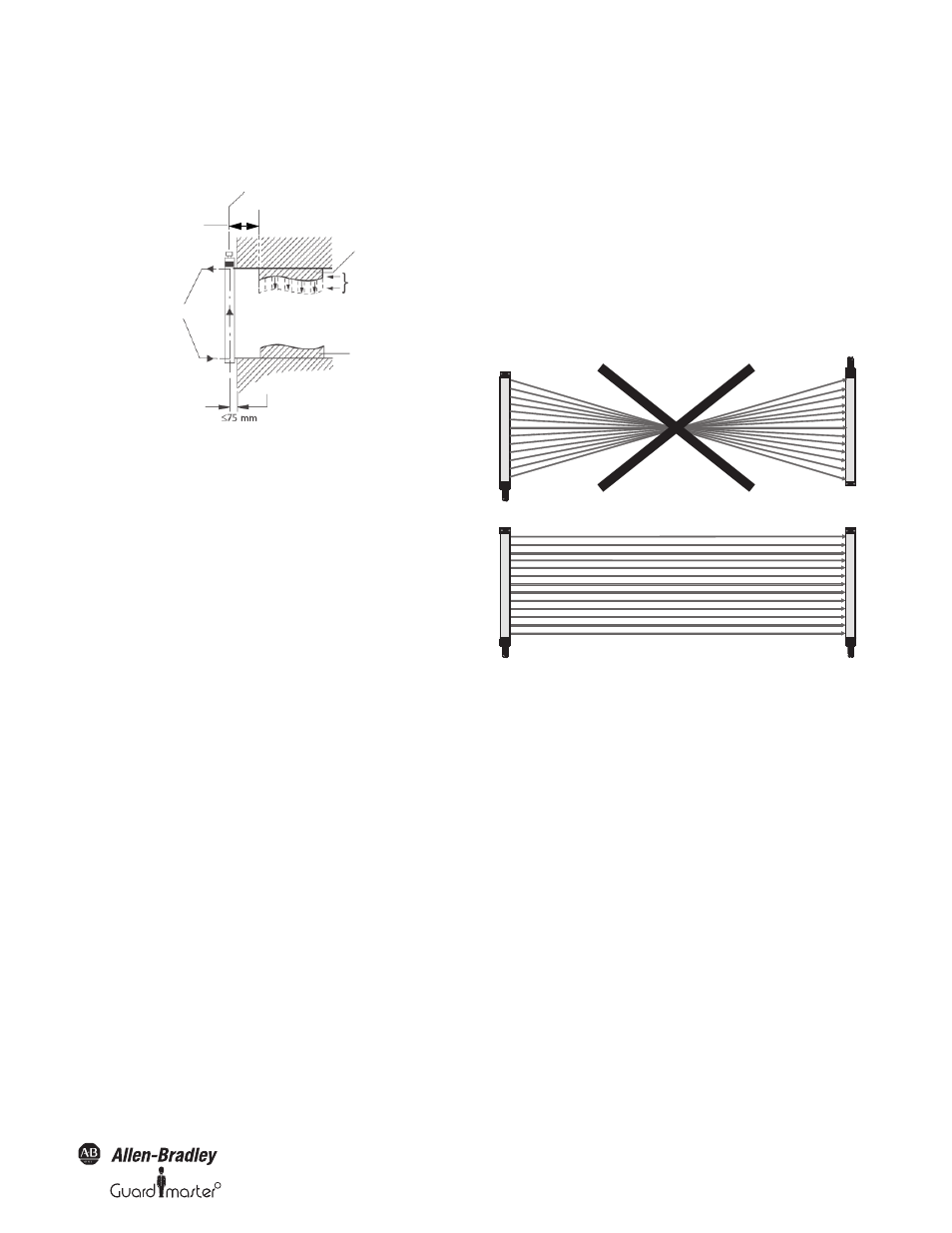
Figure 8: Layout of the transmitter/receiver
Multiple GuardShield Micro 400
When two or more GuardShield Micro 400s are mounted in close
proximity to one another, it may be possible for the receiver of
one GuardShield Micro 400 pair to receive infrared light from the
transmitter of another GuardShield Micro 400 pair.
There are various techniques to prevent or eliminate the
possibility of optical interference from light curtains mounted in
the same plane. The simplest method is to alternate transmitter
and receiver pairs so that the receiver from a second pair is facing
away from the transmitter of another light curtain pair in close
proximity. It is also possible to place a physical barrier between
pairs to prevent the infrared light from reaching another light
curtain pair.
Middle of Depth of Protective Field
Safety Distance
Point of Operation
Top of tool
Bottom of tool
To avoid the possibility of
standing between the protective
field and the point of operation,
the distance must be
maintained.
Protective Field Marking
Machine stop
time
Transmitter
Receiver
Transmitter
Receiver
Incorrect
Correct