18 pin molex output connectors, 18 pin output connectors, Flatpac-en/en mi design guide – Vicor FlatPAC-EN MI EN Compliant Autoranging Switchers User Manual
Page 8
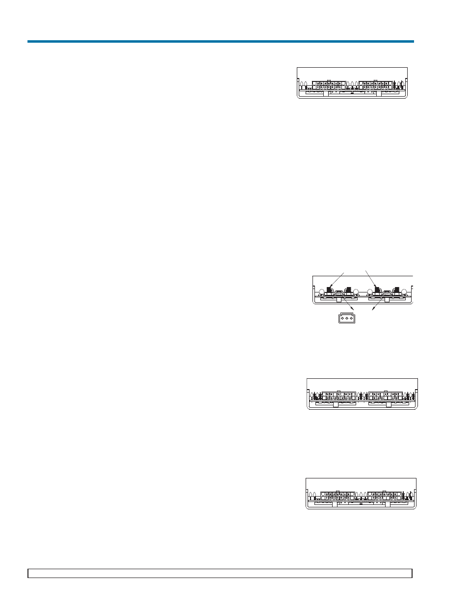
Installing power connectors on outputs with 18 pin Molex connectors
(only half and/or quarter bricks used):
• The output M1 slot only accepts a Micro module. J2-7, J2-8, J2-13 and
J2-16 are positive, while pins J2-9, J2-15, J2-17 and J2-18 are the
returns.
• The output M2 slot only accepts a Micro module. J2-1, J2-4, J2-10, J2-
11 are positive, while pins J2-2, J2-3, J2-5 and J2-12 are the returns.
• The output M3 slot only accepts a Micro module. J3-7, J3-8, J3-13
and J3-16 are positive, while pins J3-9, J3-15, J3-17 and J3-18 are the
returns.
• The output M4 slot only accepts either a Mini or a Junior module. J3-1,
J3-10 and J3-11 are positive while pins J3-2, J3-3, and J3-12 are the
returns.
• For this 18 pin housing, use Molex mating receptacle #39-01-2180 with
#39-00-0039 terminals.
• Attach 18-24 AWG stranded wire using Molex tool #11-01-0197
• Note: The molex connectors are limited to 9A/pin (27A per output)
See page 11 for detailed diagrams of output connections.
Sense Connections
The FlatPAC-EN/EN MI is shipped with Autosense installed (For more informa-
tion on Autosense, refer to page 16)
Sense Connections for stud outputs (only full and/or half bricks used):
• For Remote Sense, connect Remote Sense wires to Remote Sense/Trim Pin
Access Connector J1 or J2 for single output and J1/J2 for dual outputs.
* Connector pins J1-2 and J2-2 are the + Senses and J1-3 and J2-3 are
the -Senses.
• Use Molex mating receptacle #50-57-9403 with #16-02-0103 terminals.
• Attach terminals to 24-30 AWG stranded twisted pair wire using Molex tool #
11-01-0208.
• Attach opposite end of sense lines to their respective outputs to point where
regulation is desired. Verify that sense lines are not cross-connected.
Sense Connections on 18 pin molex output connectors (only half bricks used):
• If Remote Sense is desired, connect Remote Sense wires to the sense lines of
Connector J2 for output 1 and J3 for outputs 2 and 3.
* For Output M1, J2- 13 is the +Sense and J2-15 is the -Sense.
* For Output M2, J3-13 is the +Sense and J3-15 is the -Sense.
* For Output M3, J3-4 is the +Sense and J3-5 is the -Sense.
• Use Molex mating receptacle #39-01-2180 with #39-00-0039 terminals.
• Attach 18-24 AWG stranded twisted pair wire using Molex tool #11-01-
0197.
Sense Connections on 18 pin output connectors (only half and/or quarter bricks
used):
• If Remote Sense is desired (available only on output M4), connect Remote
Sense wires to sense lines of Connector J3
* Remote Sense is NOT available for Micro modules and hence is not
available on outputs M1, M2 and M3.
* On output M4, J3- 4 is the +Sense and J3-5 is the -Sense.
• Use Molex mating receptacle #39-01-2180 with #39-00-0039 terminals.
• Attach 18-24 AWG stranded twisted pair wire using Molex tool #11-01-0197
Pg 8
Vicor 800-735-6200 Westcor Division 408-522-5280 Applications Engineering 800-927-9474
03-000050 rev A
FlatPAC-EN/EN MI Design Guide
OUTPUTS M1 & M2
OUTPUTS M3 & M4
18 PIN MOLEX OUTPUT CONNECTORS
J2
J3
PIN DESCRIPTION
1
+V OUT M2
2 -V OUT M2
3 -V OUT M2
4 +V OUT M2
5
- VOUT M2
6 TRIM M1
7 +V OUT M1
8 +V OUT M1
9 -V OUT M1
PIN DESCRIPTION
10 +V OUT M2
11 +V OUT M2
12 -V OUT M2
13 + VOUT M1
14 TRIM M2
15 - VOUT M1
16 +V OUT M1
17 - V OUT M1
18 - V OUT M1
PIN DESCRIPTION
1
+V OUT M4
2 -V OUT M4
3 -V OUT M4
4 + SENSE M4
5
- SENSE M4
6 TRIM M3
7 +V OUT M3
8 +V OUT M3
9 -V OUT M3
PIN DESCRIPTION
10 +V OUT M4
11 +V OUT M4
12 -V OUT M4
13 + VOUT M3
14 TRIM M4
15 - VOUT M3
16 +V OUT M3
17 - V OUT M3
18 - V OUT M3
1
9
10
18
1
9
10
18
OUTPUT M1
OUTPUT M2
10-32 STUDS
+
M2
J2
-
M1
-
J1
+
STUD OUTPUT CONNECTORS
1
2
3
1 Trim Pin
2 + Remote Sense
3 - Remote Sense
Pin
OUTPUTS M2 & M3
OUTPUT M1
18 PIN MOLEX OUTPUT CONNECTORS
J2
J3
J2-13 + SENSE M1
J2-15 - SENSE M1
J3-4 + SENSE M3
J3-5 - SENSE M3
J3-13 + SENSE M2
J3-15 - SENSE M2
1
18
9
10
1
9
10
18
+S
-S
+S
-S
+S
-S
OUTPUTS M1 & M2
OUTPUTS M3 & M4
18 PIN OUTPUT CONNECTORS
J2
J3
M4 accepts 1 Mini or 1
Junior
J3-4 + SENSE M4
J3-5 - SENSE M4
1
9
10
18
1
9
10
18
M1, M2, M3 accept Micro modules
No sense connections are available
for Micro modules
+S
-S