Interface connections, Flatpac-en/en mi design guide, Mbj1 – Vicor FlatPAC-EN MI EN Compliant Autoranging Switchers User Manual
Page 13: J2/j3
03-000050 rev A
Vicor 800-735-6200 Westcor Division 408-522-5280 Applications Engineering 800-927-9474 Pg. 13
FlatPAC-EN/EN MI Design Guide
Interface Connections
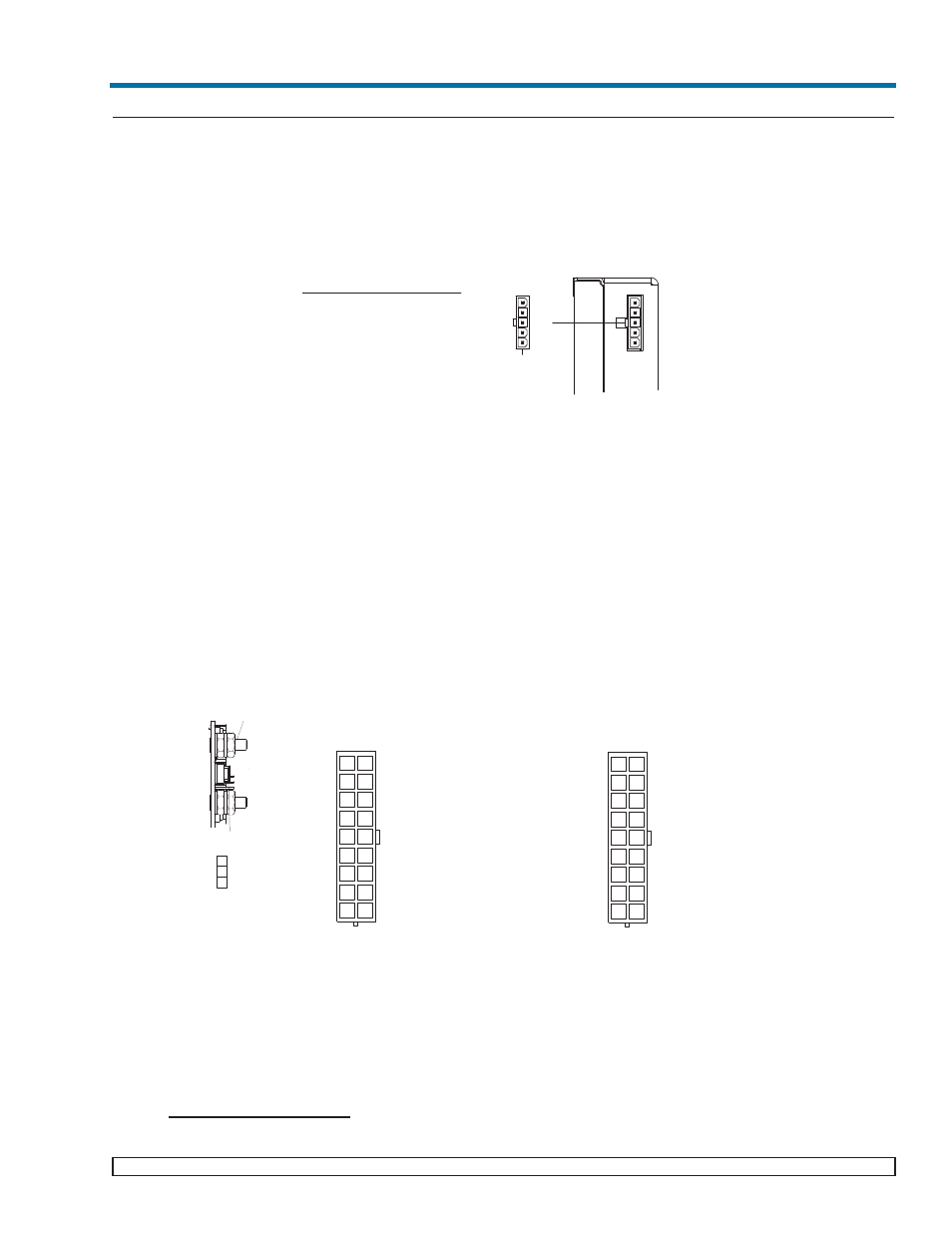
Chassis Input Power Terminals (MBJ1)
Input AC power is applied through connector MBJ1 using Molex mating connector 39-01-4051. Use 16 AWG
wire with Molex Socket Pin 39-00-0090 and Crimp Tool 11-01-0199.
A fault clearing device, such as a fuse or circuit breaker, with a maximum 9A rating at the power supply input is
required for safety agency compliance. It should be sized to handle the start-up inrush current of 8.5A peak at 115
Vac or 17A peak at 230 Vac.
Output Power Connections
There are two types of output power terminals available in the FlatPAC-EN. Each slot has one of the following
configurations: either 10-32 plated steel bolts or an 18 pin Molex connector (The type of output connector a
FlatPAC-EN has depends on which modules are used. See page 6 and 11. Molex connectors are limited to 9A/pin,
27A per output) The positive polarity of the stud output termination is the right bolt when viewed from the output
end. Each power output is isolated, so outputs of positive or negative polarity can be configured through proper
selection of the output reference terminal.
In order to minimize parasitic cable inductance and reduce EMI, the output power cables should be routed in close
proximity to one another, and large current loops should be avoided. To avoid excessive voltage drop, do not
undersize power cables, especially for high current outputs. Do not bulk input AC wires with the output wires
because this can couple output noise into the input wires which can increase EMI. Excessive cable inductance
coupled with large capacitive loading can introduce instability in switching power supplies. This problem can be
avoided with proper system design. Consult Vicor’s Applications Engineering Department for assistance with
applications that use long cable lengths and excessive load capacitance.
User Interface Connections
Signal Ground (CBJ1-1)
MATING CONNECTOR:
HOUSING: MOLEX (39-01-4051)
SOCKET CRIMP 16 AWG: MOLEX (39-00-0090)
CRIMP TOOL: MOLEX (11-01-0199)
MBJ1 A/C INPUT
MBJ1
N/C
N/C
L1
L2/N
GND
Figure 2: Input Power Terminal MBJ1
2
3
4
5
6
7
8
11
12
13
14
15
16
17
1 10
9 18
1
N/C
2
N/C
3
N/C
4
N/C
5
N/C
6
TRIM M1
7
+V OUT M1
8
+V OUT M1
9
-V OUT M1
10 N/C
11 N/C
12 N/C
13 + SENSE M1
14 N/C
15 - SENSE M1
16 +V OUT M1
17 - V OUT M1
18 - V OUT M1
PIN DESCRIPTION
PIN DESCRIPTION
10-32 OUTPUT STUDS
TRIM
1
J1/J2 SENSE/TRIM
PIN CONNECTOR
3
2
- SENSE
+ SENSE
B. 18 PIN MOLEX OUTPUT CONNECTOR
A. STUD OUTPUT
J2 (18 PIN OUTPUT, SENSE
AND TRIM PIN CONNECTOR)
-V OUT
+V OUT
Outputs M2 and M3 (Using 2 Minis or 2 Juniors)
1
+V OUT M3
2
-V OUT M3
3
-V OUT M3
4
+ SENSE M3
5
- SENSE M3
6
TRIM M2
7
+V OUT M2
8
+V OUT M2
9
-V OUT M2
10 +V OUT M3
11 +V OUT M3
12 -V OUT M3
13 + SENSE M2
14 TRIM M3
15 - SENSE M2
16 +V OUT M2
17 - V OUT M2
18 - V OUT M2
PIN DESCRIPTION
PIN DESCRIPTION
J3 (18 PIN OUTPUT, SENSE
AND TRIM PIN CONNECTOR)
J2/J3
2
3
4
5
6
7
8
11
12
13
14
15
16
17
1 10
9 18
Outputs M3 and M4 (Using 1 Micro
and 1 Mini or 1 Junior)
1
+V OUT M4
2
-V OUT M4
3
-V OUT M4
4
+ SENSE M4
5
- SENSE M4
6
TRIM M3
7
+V OUT M3
8
+V OUT M3
9
-V OUT M3
10 +V OUT M4
11 +V OUT M4
12 -V OUT M4
13 + VOUT M3
14 TRIM M4
15 - VOUT M3
16 +V OUT M3
17 - V OUT M3
18 - V OUT M3
PIN DESCRIPTION
PIN DESCRIPTION
J3 (18 PIN OUTPUT, SENSE
AND TRIM PIN CONNECTOR)
1
+V OUT M2
2
-V OUT M2
3
-V OUT M2
4
+V OUT M2
5
- VOUT M2
6
TRIM M1
7
+V OUT M1
8
+V OUT M1
9
-V OUT M1
10 +V OUT M2
11 +V OUT M2
12 -V OUT M2
13 + VOUT M1
14 TRIM M2
15 - VOUT M1
16 +V OUT M1
17 - V OUT M1
18 - V OUT M1
PIN DESCRIPTION
PIN DESCRIPTION
J2 (18 PIN OUTPUT, SENSE
AND TRIM PIN CONNECTOR)
J2/J3
Output M1 (Using 1 Mini or 1 Junior)
Outputs M1 and M2 (Using 2 Micros)
B. 18 PIN MOLEX OUTPUT CONNECTOR
(Note: The Molex connectors are limited to 9A/pin (27A/output)
Figure 3: Output Power Connections