Vicor FlatPAC-EN MI EN Compliant Autoranging Switchers User Manual
Page 5
Technical Description
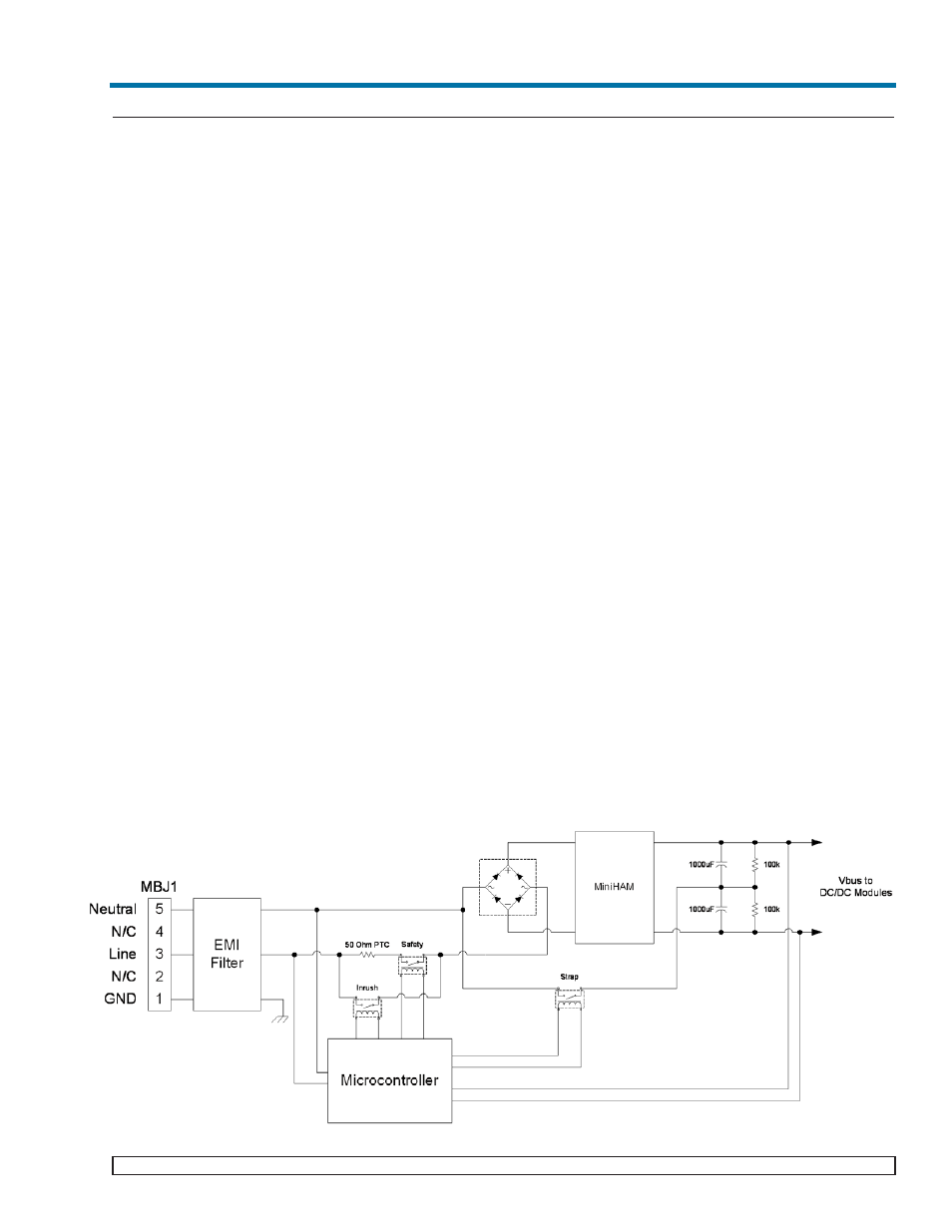
The FlatPAC-EN/EN MI consists of an off-line single phase autoranging front end, EMI filter, customer interface,
power supply control circuit, associated housekeeping circuits, a MiniHAM module and a selection of Vicor’s VI-
200/VI-J00 and/or Maxi/Mini/Micro DC-DC converters.
The MiniHAM was specifically designed for EN compliance using passive filtering. Unlike active PFC solutions,
the MiniHAM generates no EMI, greatly simplifying and reducing system noise filtering requirements. It is also
considerably smaller and more efficient than active alternatives and improves the unit’s MTBF. It will provide har-
monic current compliance at 230Vac input up to 425W of output power. Input AC mains voltage is applied to input
connector MBJ1 (see page 7) and the input current is passed through an EMI filter designed to meet conducted
noise limit of EN 55022, Classes A and B specifications (certain configurations meet EN55022 Class B. Consult
Factory.)
At start-up, the microcontroller verifies that the input voltage is within the specified operating range. Once this
occurs, the microcontroller closes the safety relay and puts the autoranging front-end in the correct mode (closing
or opening the Doubler relay). The autoranging front-end has two modes, the doubler mode (90Vac - 132Vac) or
bridge rectifier mode (180Vac-264Vac, 250Vdc-380Vdc). Inrush current is limited by a PTC thermistor. The PTC
is shunted out (by closing the Inrush relay) when the output voltage has charged up the bus capacitors within the
specified range (205Vdc-390Vdc). Approximately 1 second after the application of the input voltage, the bus volt-
age is within operating limits and the AC OK signal asserts to a TTL "1", indicating the input power is OK. After
AC OK is asserted high, the user can now control the power outputs.
Output voltage conversion is achieved by Vicor’s 300Vin family of Zero-Current-Switching (ZCS) DC-DC con-
verters. These are forward converters in which the main switching element switches at zero current. This patented
topology has a number of unique attributes: low switching losses; high frequency operation, resulting in reduced
size for magnetics and capacitors; excellent line and load regulation; wide adjustment range for output; low
EMI/RFI emission and high efficiencies.
At initial power-up, all outputs are disabled to limit the inrush current and to allow the DC bus potential to settle
to the correct operating level. A low-power transformer flyback circuit converts the high voltage DC bus into regu-
lated low voltage to power the internal housekeeping circuits as well as the auxiliary +5Vs located in the interface
connector.
An output Enable/Disable function is provided to control Vicor’s DC-DC converters. If the Enable/Disable control
pin is pulled low, the modules output is disabled. The nominal delay associated for an output to come up when
measured from release of the Enable/Disable pin is 9-12 ms. The General Shutdown function controls all outputs
simultaneously and works in a similar manner.
03-000050 rev A
Vicor 800-735-6200 Westcor Division 408-522-5280 Applications Engineering 800-927-9474 Pg. 5
FlatPAC-EN/EN MI Design Guide