Flatpac-en/en mi “quick install” instructions, Mbj1, N/c l1 l2/n gnd – Vicor FlatPAC-EN MI EN Compliant Autoranging Switchers User Manual
Page 7: Flatpac-en/en mi design guide
FlatPAC-EN/EN MI “Quick Install” Instructions
(For mechanical drawings, see page 10)
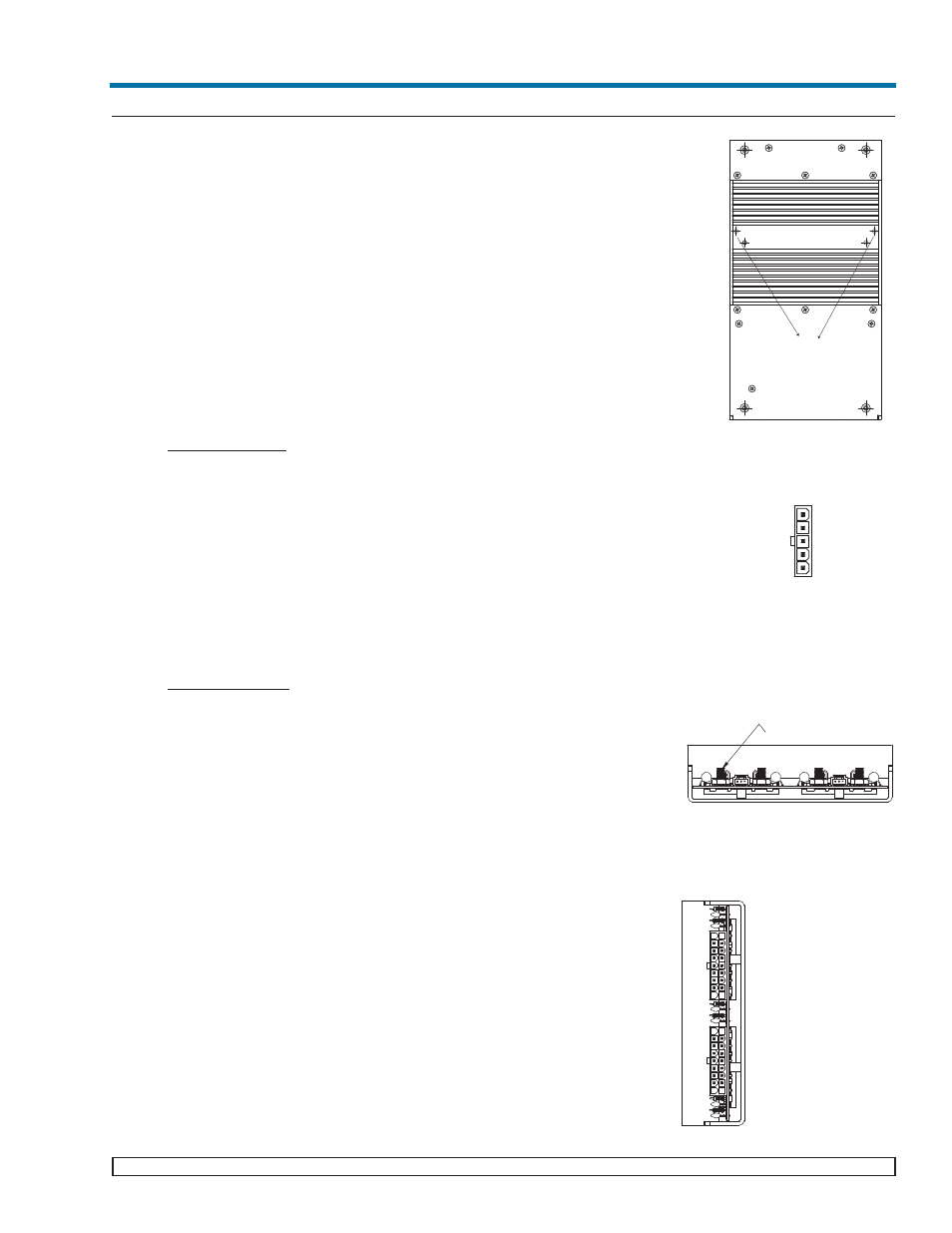
Mounting the FlatPAC-EN/EN MI
• Mount the FlatPAC-EN on the bottom (cannot be mounted from the front).
• For standard mounting (forced air cooling), use A1, A2, A3, A4 mount-
ing holes.
For standard mounting (conduction cooling), use A1, A2, A3, A4, B and B2
mounting holes.
• For a Vicor 2 Up FlatPAC retrofit replacement, use C1 and C2 as these
two are identical to the mounting holes on the FlatPAC.
• For increased ruggedness, use additional mounting holes to secure the power
supply.
• Use #8-32 or 4mm mounting screws. For mounting holes A1, A2, A3 and
A4, the maximum penetration should not exceed 0.125 in. (3mm). For mount-
ing holes B1, B2, C1 and C2, do not exceed maximum penetration of 0.250 in.
(6 mm).
* The maximum allowable torque is 5 in. lbs.,
Input Connections
Input Power MBJ1
• Apply input AC power connector MBJ1 using a maximum torque of 5 in. lbs
• Place a fuse or circuit breaker in the input line for safety requirements
(9A).
• Use Molex mating receptacle 39-01-4051, terminals 39-00-0090 and crimp
tool Molex # 11-01-0199.
Output Connections (Refer to page 6 for more information on configuration
layout and output connector type)
Note: The type of output connector a FlatPAC-EN has depends on which modules are
used. Also, outputs with molex connectors are limited to 9A/pin (27A per output).
Power Connections
Installing power connectors on outputs with 10-32 stud connectors (only full
and/or half bricks used):
• Install #10 ring lugs on output studs
* The right stud is positive and the left stud is the return when viewed from the
output end.
• Remove the nut and place ring lug over output stud.
• Replace and tighten the nut to a torque of 10 inch pounds. Do Not Over-
Tighten Nuts.
Installing power connectors on outputs with 18 pin Molex connectors (only
half bricks used):
• The output M1 slot accepts either a Mini or a Junior module. J2-7, J2-8, J2-
16 are positive, while pins J2-9, J2-17 and J2-18 are the returns.
• J2-1, J2-2, J2-3, J2-4, J2-5, J2-10, J2-11, J2-12 and J2-14 are not connected.
• The output M2 slot accepts either a Mini or a Junior module. J3-7, J3-8,
and J3-16 are positive while pins J3-9, J3-17 and J3-18 are the returns.
• The output M3 slot accepts either a Mini or a Junior module. J3-1, J3-10,
J11 are positive while pins J3-2, J3-3, J3-12 are the returns.
• For this 18 pin housing, use Molex mating receptacle #39-01-2180 with #39-
00-0039 terminals.
• Attach 18-24 AWG stranded wire using Molex tool #11-01-0197.
• Note: The molex connectors are limited to 9A/pin (27A per output)
03-000050 rev A
Vicor 800-735-6200 Westcor Division 408-522-5280 Applications Engineering 800-927-9474 Pg. 7
FlatPAC-EN/EN MI Design Guide
Identical mounting
holes (CI & C2) to Vicor's
2 UP FlatPAC
C1
C2
B1
B2
A3
A4
A1
A2
MBJ1
N/C
N/C
L1
L2/N
GND
OUTPUT M1
OUTPUT M2
10-32 STUDS
+
J2
-
M1
-
J1
+
STUD OUTPUT CONNECTORS
OUTPUTS M2 & M3
OUTPUT M1
18 PIN MOLEX OUTPUT CONNECTOR
J2
J3
1
18
9
10
1
9
10
18
PIN DESCRIPTION
1
N/C
2
N/C
3
N/C
4
N/C
5
N/C
6 TRIM M1
7 +V OUT M1
8 +V OUT M1
9 -V OUT M1
PIN DESCRIPTION
10 N/C
11 N/C
12 N/C
13 + SENSE M1
14 N/C
15 - SENSE M1
16 +V OUT M1
17 - V OUT M1
18 - V OUT M1
J2
PIN DESCRIPTION
1
+V OUT M3
2 -V OUT M3
3 -V OUT M3
4 + SENSE M3
5
- SENSE M3
6 TRIM M2
7 +V OUT M2
8 +V OUT M2
9 -V OUT M2
PIN DESCRIPTION
10 +V OUT M3
11 +V OUT M3
12 -V OUT M3
13 + SENSE M2
14 TRIM M3
15 - SENSE M2
16 +V OUT M2
17 - V OUT M2
18 - V OUT M2
J3