Current share boards - optional feature – Vicor FlatPAC-EN MI EN Compliant Autoranging Switchers User Manual
Page 26
Pg 26
Vicor 800-735-6200 Westcor Division 408-522-5280 Applications Engineering 800-927-9474
03-000050 rev A
FlatPAC-EN/EN MI Design Guide
Current Share Boards - Optional Feature
"
Current sharing" also known as Load Sharing, is the
ability to divide the output current evenly across all
active power supplies. This greatly reduces stresses
on each power supply and allows them to run cooler,
resulting in higher reliability. Standard "current shar-
ing" techniques typically utilize shunt resistors or
Hall Effect devices to measure the current from each
power supply. Power shunt resistors continually dis-
sipate power and require cooling especially when
dealing with high output currents of >100Amps. Hall
Effect devices measure magnetic fields generated by
current flowing through a conductor and, although
they dissipate no power, they tend to be large and
expensive.
First developed by Westcor Engineering for parallel-
ing MegaPAC supplies, the Box-to-Box Current
Share Board or CSB allows two or more Vicor power
supplies to current share by utilizing the inherent voltage
drop produced in the negative output return cable. This
eliminates the need for additional shunt resistors or
expensive Hall Effect devices and provides a simple 5
wire connection method to achieve a +/-1mV accuracy
between the Negative Output power rails. This accuracy
translates to a 1% current sharing if there is a total of
100mV conductional voltage drop in the negative return
path.
Constructed as a current source to drive the Trim pin of
a Vicor module, the design uses an accurate comparator
circuit to monitor the power returns. In addition, the cir-
cuit is unidirectional and can only trim an output voltage
up. The benefit is that only the supply that is supporting
less current is adjusted up. This action balances the cur-
rents to the load by matching the output voltages of the
supplies. In the case of one supply failing, the circuit
will attempt to trim the failed supply only. This will
leave the remaining functional supply alone to provide
power to the load at its nominal voltage. Thus the circuit
also offers simple redundancy. In addition, because CSB
functions as a current source, the Trim outputs (T1 and
T2) of the CSB can be placed in parallel to create a sum-
ming node. This allows current sharing between more
than two supplies by paralleling the T2 output of one
CSB circuit with the T1 output of the next CSB.
Please note: The CSB is not intended for use in Hotswap
Applications.
Requirements:
1. For proper operation, the power supplies being paral-
leled should be enabled at the same time.
2. -Out conductors must be of equal length and wire
gauge.
Separate -Out conductors must be used from each supply
to the load, or the use of a "Y" connection to a common
point
must be used as shown in figure 1. Each leg of the "Y"
must have a minimum of a few millivolts of drop in order
for proper operation. 50mV to 100mV of drop will pro-
vide from 5% to 1% accuracy.
3. -V1 and -V2 for all Box-to-Box circuits must be con-
nected directly at the negative output power studs or ter-
minals to achieve accurate current sharing.
4. D* can be added if redundancy is needed. If redun-
dancy is not required, D* can be replaced with direct
wire connections.
5. When using D*, the Power input should be connected
on the cathode side of the paralleling diodes as shown
above.
6. Terminate Sense Leads either locally or remotely as
shown in figure 1.
7. For paralleling more than 2 supplies consult factory
for assistance.
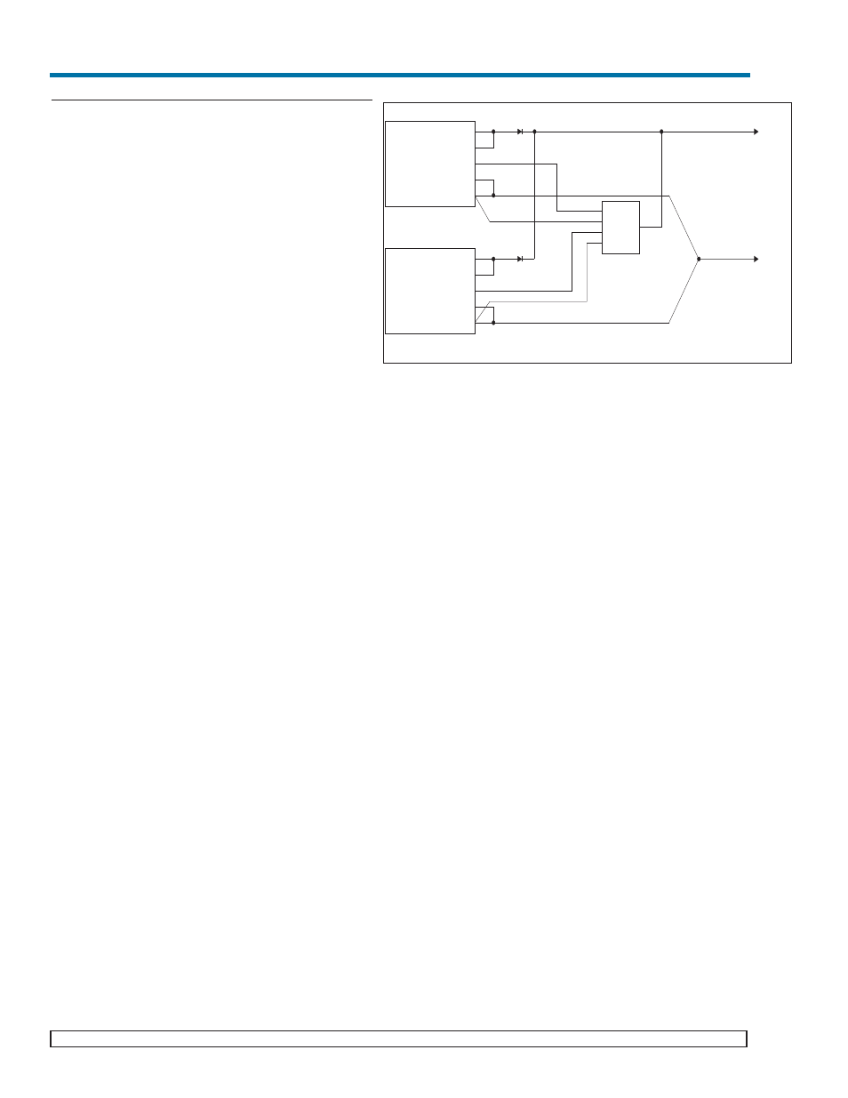
Figure 1. CSB Interconnect Example
Supply # 1
5V @ 120A
+OUT
+S
-OUT
-S
TRIM
Supply # 2
5V@120A
+OUT
+S
-OUT
-S
TRIM
T1
-V1
T2
-V2
Power
+VOUT
-VOUT
D*
D*
CSB02
Black
White
Brown
Yellow
Red