Vicor FlatPAC-EN MI EN Compliant Autoranging Switchers User Manual
Page 17
03-000050 rev A
Vicor 800-735-6200 Westcor Division 408-522-5280 Applications Engineering 800-927-9474 Pg. 17
FlatPAC-EN/EN MI Design Guide
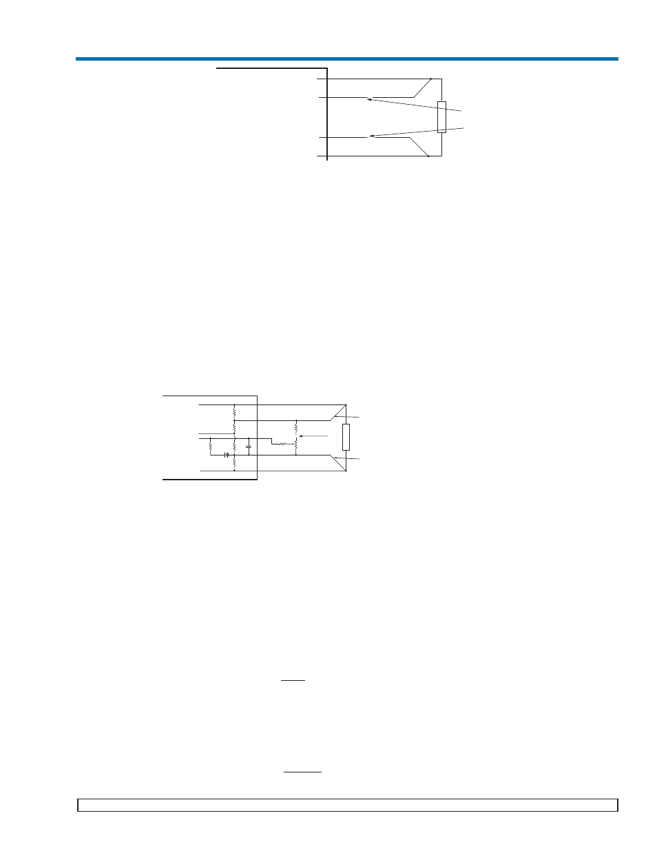
Note: Remote sense is not available for output configurations using the Micro modules.
External Trim (Not applicable when using BatMod current source)
The Trim pin can be used for external control of the output voltage. Trim connections on single and dual output
connector for output M1 is J1-1 while for output M2 is J2-2. Trim connections on triple output connectors for out-
put M1 is J2-6, for output M2 is J3-6, and for output M3 is J3-14. Trim connections for quadruple output connec-
tors on outputs M1 and M2 is J2-6 and J2-14 respectively, and for outputs M3 and M4 is J3-6 and J3-14 respec-
tively. A 10% increase to the trim pin voltage will result in a 10% increase in output voltage. Reducing the trim
pin voltage by 10% will result in a 10% decrease in output voltage.
OUTPUT MODULE
V
ref
R
TH
VI-200/VI-J00
≥3.3V
2.5V
10k
Ω
VI-200/VI-J00 <3.3V
0.97V
3.88k
Ω
Maxi/Mini/Micro (Predefined)
1.23V
1k
Ω
Maxi/Mini/Micro (Userdefined)
1.23V
Consult Factory
Table 1. Module Internal Reference Voltages and Thevenin Resistances.
Example:
±10% trim adjust on a 12V nominal output.
Figure 8 shows a typical variable trim circuit. Using a 10k trimpot (R7), the resistor values for R6 and R8 can be
calculated as follows:
V
1
= V
ref
+ 10% = 2.75V
Given: V
ref
= 2.5V (see Table 1)
I
R5
= (2.75V - V
ref
)/R
TH
= (2.75V - 2.5V)/10k
Ω = 25μA
Given: R
TH
= 10k
Ω (see Table 1)
Setting the bottom limit:
V
R6
= 2.5V - 10% = 2.25V
And since I
R5
= I
R6
= 25
μA,
R6 = V
R6
/I
R6
= 2.25V/25
μA = 90kΩ
V
2
= V
1
+ V
R6
= 2.75V + 2.25V = 5V
I
R7
= V
2
/R7 = 5V/10k
Ω = 500μA
I
R8
= I
R7
+ I
R6
= 525
μA
V
R8
= (V
nom
+10%) - V
2
= 13.2V - 5V = 8.2V
Given: V
nom
= 12V
R8 = V
R8
/I
R8
= 8.2V/525
μA = 15.62kΩ
(Remote Sense)
Load
+Out
+Sense
-Sense
-Out
Use 24-30 AWG
Twisted Pair Wires
R5
V
Ref
Trim
R6
R8
R7
To Error
Amplifier
R4
R3
R2
R1
+
+
V
2
V
1
-
-
RTH
Use 24-30 AWG
Twisted Pair Wires
Load
+Out
+Sense
-Sense
-Out
Use 24-30 AWG
Twisted Pair Wires
Figure 7: Remote Sense
Figure 8: External Trim
Note: Trimming up by more than 15%
may induce over voltage protection.