Field wiring information – TCI HG7 User Manual
Page 50
K I T P A C K A G E O P T I O N ( K P )
KIT PACKAGE OPTION
HG7 I, O, & M Manual
48
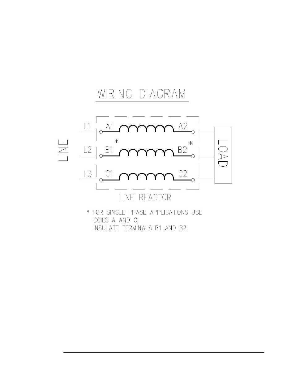
Field Wiring Information
Below is the typical wiring diagram for the 3-phase reactor applied to the front end of the Variable
Frequency Drive (VFD). Single-phase applications are acceptable, however, it is important to size the unit
based on the single phase Full Load Amperage of the VFD. The input and output connections should be on
terminals A and C to ensure proper performance.