Drawings, Schematic diagrams, Outline and mounting dimension drawings – TCI HG7 User Manual
Page 18: Additional typical drawings
I N T R O D U C T I O N
INTRODUCTION
HG7 I, O, & M Manual
16
Drawings
Typical Schematic Diagrams and Outline and Mounting Dimension Drawings
Typical HG7 drawings are provided on the following pages. These drawings provide general
information describing your HG7 harmonic filter. More specific information is provided by the
drawings shipped with the unit. Be sure to carefully review the information on the provided drawings.
The information on the drawings provided with the filter takes precedence over the information
provided in this manual.
Schematic Diagrams
The schematic diagram shows the details of the HG7 circuitry. The power circuit schematic shows the
variations in input and output power connections.
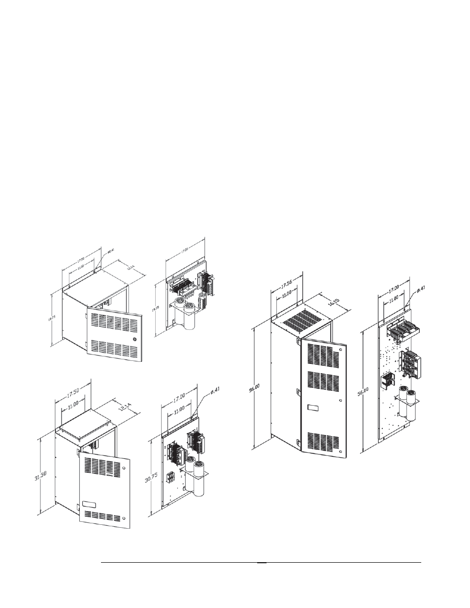
Outline and Mounting Dimension Drawings
Outline and mounting dimension drawings show the overall enclosure dimensions, the conduit access
areas and the wiring connection points. The major internal components are shown pictorially.
Additional Typical Drawings
Some additional typical drawings are available for downloading at http://www.transcoil.com.