Protection monitor display fault codes, Table 8 – fault code troubleshooting procedures – TCI HG7 User Manual
Page 37
P O W E R M O N I T O R P A C K A G E O N L Y
POWER MONITOR OPTION
HG7 I, O, & M Manual
35
Protection Monitor Display Fault Codes
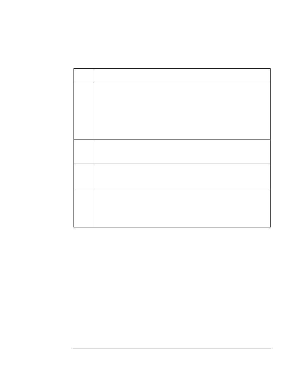
If the Protection Monitor display shows a Fault Code (F01 to F33), follow the troubleshooting
procedure provided in Table 8. If a Fault Code is displayed, the Filter Disabled LED will be
illuminated and the Fault Alarm Relay will be de-energized.
Table 8 – Fault Code Troubleshooting Procedures
FAULT
Code
Troubleshooting Procedure
F01
External Fault
This Fault Code indicates a fault in an HG7unit other than the one displaying the "F01"
Fault Code.
In a system that has multiple sections, each monitored with an HG2, any HG2 may detect
a fault and in turn disconnect all the harmonic filters linked via the serial connection. The
unit detecting the fault will display the appropriate Fault Code while all others in the series
will display “F01.” The fault may only be cleared from the harmonic filter section
experiencing the fault. Once the fault is cleared the other units will revert to Normal
Operation. In single board configurations, there is a jumper wire installed in connector J1-
8 & J1-10. Troubleshoot by verifying continuity at the Protection Monitor between J1-8 &
J1-10.
F02
Door Interlock Fault
This Fault Code indicates the optional door interlock switch is open.
When this option is not supplied there is a jumper wire installed between TB2-7 &TB2-8.
Troubleshoot by verifying continuity between J6-1 & J6-8.
F03
Over-temperature Fault
This Fault Code indicates the optional over temperature switch open.
When this option is not supplied there is a jumper wire installed between TB2-5 & TB2-6.
Troubleshoot by verifying continuity at the Protection Monitor between J6-1 & J6-6.
F04
Serial Interlock Fault
This fault indicates the serial link between multiple boards is open or wired incorrectly.
Verify that from board number one J1-8 is connected to board two J1-10 and board two
J1-8 to board “N” J1-10 and board “N” J1-8 is connected to board one J1-10 thus
completing the daisy chain serial loop. In single board configurations, there is a jumper
wire installed in connector J1-8 & J1-10. Trouble shoot by verifying continuity at the
Protection Monitor between J1-8 & J1-10.