Table 5 – operating parameter display, Fault detection – TCI HG7 User Manual
Page 33
P O W E R M O N I T O R P A C K A G E O N L Y
POWER MONITOR OPTION
HG7 I, O, & M Manual
31
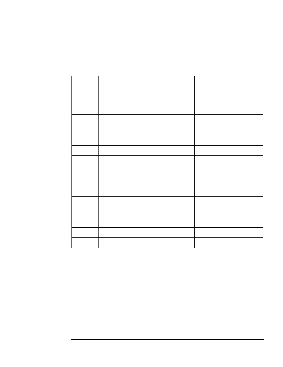
indicates that the displayed value is the average of the individual phase values. "L 1," "L 2," & "L 3"
indicate the display of individual phase values. "L r," indicates that the displayed value is the total of
the phase values. To change the "L *" selection, press and hold the SELECT key to scroll to the desired
selection. The "L 1," "L 2," & "L 3" selections are available for all of the parameters. The “L A”
selection is available for Filter Current “C,” Line Voltage “U,” Line Current “A” and Power Factor
“PF.” The "L r” selection is available for Real Power “P” and Apparent Power “UA.”
Table 5 – Operating Parameter Display
Parameter
Name
Parameter Value
Parameter
ID
Parameter Value
OFF
Not in run and no faults
A
Line Current (total RMS amps)
C
Filter current (total RMS amps)
A H
Line harmonic current distortion
(% THD)
C H
Filter harmonic current distortion
(% THD)
A 1
Line 1st harmonic current
(fundamental RMS amps)
C 1
Filter 1st harmonic current
(fundamental RMS amps)
A 5
Line 5th harmonic current
(RMS amps)
C 5
Filter 5th harmonic current
(RMS amps)
A 7
Line 7th harmonic current
(RMS amps)
C 7
Filter 7th harmonic current
(RMS amps)
A11
Line 11th harmonic current
(RMS amps)
C11
Filter 11th harmonic current
(RMS amps)
A13
Line 13th harmonic current
(RMS amps)
C13
Filter 13th harmonic current
(RMS amps)
P
Real Power (kW)
U
Line voltage L-N (total RMS volts)
L-N approx. 277 for a 480 volt
system and approx. 139 for a 240
volt system
U A
Apparent Power (kVA)
U H
Line harmonic voltage distortion
(% THD)
PF
Power Factor (%)
U 1
Line 1st harmonic voltage
(fundamental RMS volts)
*L A
Average value
U 5
Line 5th harmonic voltage
(RMS volts)
*L r
Total value
U 7
Line 7th harmonic voltage
(RMS volts)
*L 1
Line 1 value
U11
Line 11th harmonic voltage
(RMS volts)
*L 2
Line 2 value
U13
Line 13th harmonic voltage
(RMS volts)
*L 3
Line 3 value
* These functions are accessible by pressing the SELECT key.
Fault Detection
If a fault condition is detected by the HG2, the red Filter Disabled LED will turn on and the Fault
Alarm relay will be energized. The green Filter Enabled LED will turn off and the contactor in the
HG7 will disconnect the filter. The display will show a Fault Code, F001 to F31 as listed in Table 6. In
order to minimize nuisance trips, time delays are applied to some fault conditions as indicated in the
table.
When the fault condition has been corrected, press the UP and SELECT keys simultaneously to clear
the fault. When the fault reset clear time has expired, the red Filter Disabled LED will turn off and the
Fault Alarm relay will be de-energized. The green Filter Enabled LED will turn on, the contactor will
connect the filter and the display to the selected Operating Parameter.
In a system with multiple units, any unit may detect a fault and shut down the whole system. The other
units in the system will display “F01,” External Fault, and turn off. The fault may only be cleared by