Installation, Gas connection, Gas pipe pressure testing – Regency Energy E18 Small Gas Insert User Manual
Page 9
Regency
®
E18 Gas Fireplace Insert
9
INSTALLATION
For minimum and maximum supply pressure
see the Specifi cations table.
1. If the appliance is to be installed into an
existing chimney system, thoroughly clean
the masonry fi replace that has been chosen
for the Regency
®
Gas Fireplace.
2. The appliance is provided with an opening
on the left hand side of the control
compartment for the gas line.
Note: During any pressure testing of the
gas supply piping system that exceeds test
pressures of 1/2 psig, this appliance and its
individual shut-off valve must be disconnected
from the piping system. If test pressures equal
to or less than 1/2 psig are used then this
appliance must be isolated from the piping
system by closing its individual manual shut-off
valve during the testing.
CAUTION: If the glass is removed for
servicing, it must be replaced prior to
operating the appliance. The glass must be
fi xed in the closed position when operating.
GAS CONNECTION
Only persons licensed to work with gas piping
may make the necessary gas connections to
this appliance.
The gas connection is a 1/2" NPT accessible on
the left side of the unit. The gas line connection
may be made of rigid pipe, copper pipe or an
approved fl ex connector. (If you are using rigid
pipe, ensure that the valve can be removed
for servicing.) Since some municipalities have
additional local codes it is always best to consult
with your local authorities and the CAN/CGA
B149 installation code.
For USA installations follow local codes and/
or the current National Fuel Gas Code, ANSI
Z223.1.
When using copper or fl ex connectors use only
approved fi ttings. Always provide a union so that
gas lines can be easily disconnected for burner
or fan servicing. Flare nuts for copper lines and
fl ex connectors are usually considered to meet
this requirement.
Important: Always check for gas leaks
with a soap and water solution or gas
leak detector. Do not use open fl ame
for leak testing.
GAS PIPE
PRESSURE TESTING
The appliance must be isolated from the gas
supply piping system by closing its individual
manual shut-off valve during any pressure
testing of the gas supply piping system at test
pressures equal to or less than 1/2 psig. (3.45
kPa). Disconnect piping from valve at pressures
over 1/2 psig.
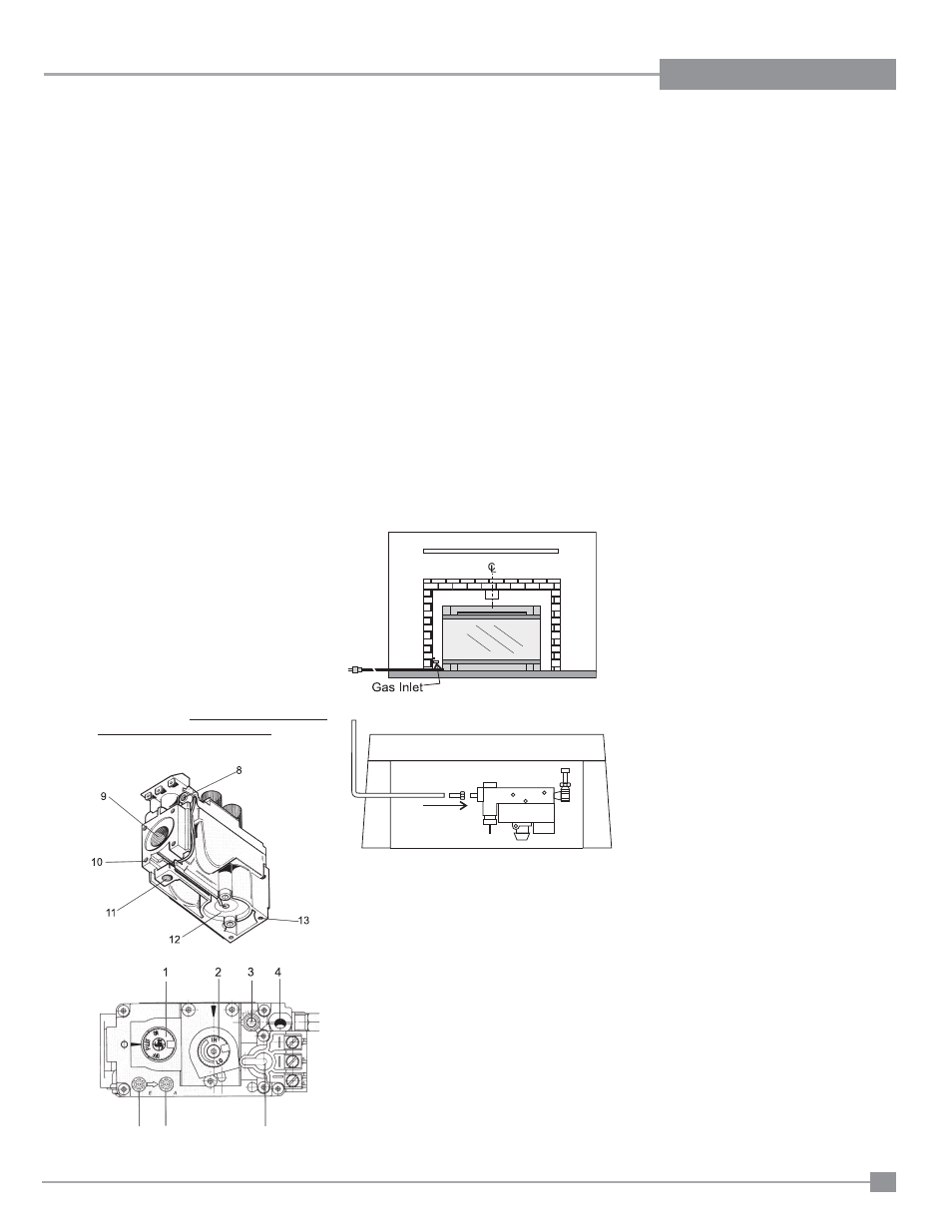
The manifold pressure is controlled by a
regulator built into the gas control, and should
be checked at the pressure test point.
Note: To properly check gas pressure, both
inlet and manifold pressures should
be checked using the valve pressure
ports on the valve.
1. Make sure the valve is in the "OFF" position.
2. Loosen the "IN" and/or "OUT" pressure
tap(s), turning counterclockwise with a 1/8"
wide fl at screwdriver.
3. Attach manometer to "IN" and/or "OUT"
pressure tap(s) using a 5/16" ID hose.
4. Light the pilot and turn the valve to "ON"
position. Read manometer.
5. The pressure check should be carried out
with the unit burning and the setting should
be within the limits specifi ed on the safety
label.
6. When fi nished reading manometer, turn
off the gas valve, disconnect the hose and
tighten the screw (clockwise) with a 1/8"
fl at screwdriver. Note: Screw should be
snug, but do not over tighten.
Diagram 2.1
Diagram 2.2
Diagram 2.3