Installation, I nstallation checklist, Materials required – Regency Energy E18 Small Gas Insert User Manual
Page 10: Venting
10
Regency
®
E18 Gas Fireplace Insert
INSTALLATION
INSTALLATION CHECKLIST
1. Verify the model of the existing appliance you
are installing into is one of the following ap-
proved units:
Montigo
EP28-2
Montigo
EP28-4
Montigo
EP28-5
Montigo
EP28-S2
Montigo 36SR (Non powervent unit)
Montigo
28F-2
Montigo
28-F
Firesong
220N
Firesong
120N
2. Verify all clearances are at least the specifi ed
clearances.
3. Inspect existing venting and appliance for signs
of wear and durability.
4. Determine the route for the electrical for
the circulation fan. The circulation fan is not
optional.
5. Determine the route for the gas supply. The valve
has a 1/2" Male Flare on the left side of the E18.
Some modifi cation may need to be made to a
hard lined gas supply to connect to the E18.
6. Clean out the existing appliance of all dust and
debris.
7. Make the appropriate modifi cations to the existing
appliance specifi ed in the "Existing Appliance
Modifi cation" section of the manual. Make sure
when done there are no sharp edges exposed
to a person during operation of the unit.
8. Unpack the E18 from the box and disassemble.
9. Install the E18 into the existing unit as per
instructions.
10. Connect Gas Supply.
11. Connect Circulation Fan Power Cord.
12. Test Fire the E18 and check gas pressures
and confi rm Circulation Fan begins operation
with 10 minutes of fi ring the unit.
13. Check draft hood for spillage as per instructions.
14. Install Trim Kit as per instructions.
MATERIALS REQUIRED
Electrical power supply is required for the circulation
fan A 120 Volt AC power cord is hooked up to the
fan. Plug the 3 wire cord into a suitable recepta-
cle. Do not cut the ground terminal off under any
circumstances. When connected with 120 volts,
the appliance must be electrically grounded in ac-
cordance with local codes, or in the absence of local
codes, with the current Canadian Electrical Code
CSA C22.1 (in Canada) or with the current National
Electrical Code ANSI/NFPA 70-1987 (in U.S.A.).
NOTE: This unit is equipped with a heat sensor
thermodisc which will prevent the blower
from operating until the unit reaches the
correct temperature.
Height
Depth
Width
23-3/8"
12-1/2"
32"
MINIMUM FIREPLACE
OPENING FOR
MASONRY AND FACTORY
BUILT FIREPLACES
The minimum fi replace opening for this Regency
gas insert are listed below.
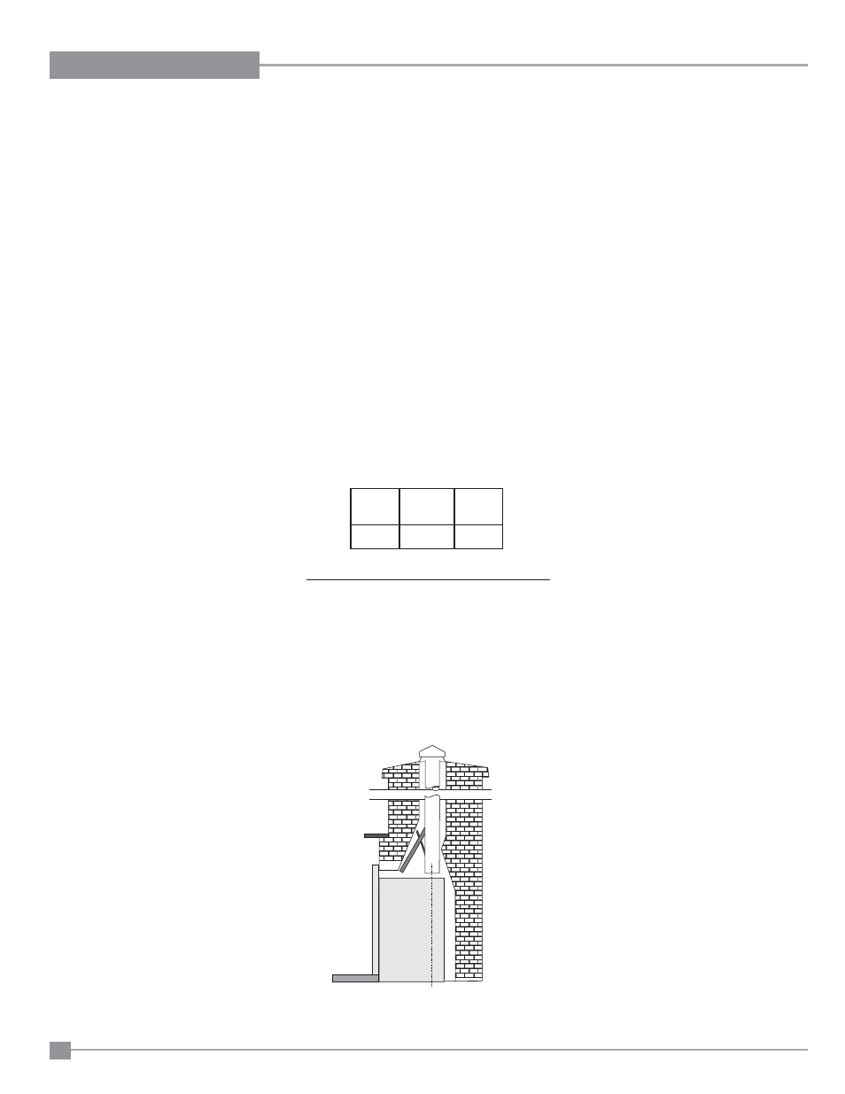
VENTING
T H E A P P L I A N C E M U S T N O T B E
CONNECTED TO A CHIMNEY FLUE
SERVING A SEPARATE SOLID FUEL
BURNING APPLIANCE.
This appliance is designed to attach to a 4" diameter
type B-Vent or double thickness approved aluminium
fl ex liner.
The fl ue collar of the appliance will fi t inside a
standard vent and may be fastened directly to the
vent using a minimum of 3 sheet metal screws or
a B-Vent, single wall vent connector.
B-Vent chimneys require a 1" clearance to com-
bustibles.
The Regency
®
Insert incorporates its own internal
draft hood, so no additional external draft hood is
required. Check periodically that the vent is unre-
stricted and an adequate draft is present when the
unit is in operation.
Before installing the vent system ensure that the
damper plate is locked into the open position and
secure to prevent the damper plate from falling
down and crushing the liner.
The appliance is equipped with a vent safety shutoff
system and a safety control system designed to
protect against improper venting of combustion
products. The appliance will not function without
being connected to a proper system.
WARNING: Operation of this heater when
not connected to a properly installed and
maintained venting system or tampering
with the vent shut-off system can result
in carbon monoxide (CO) poisoning and
possible death.
This appliance must not be connected to a chimney
fl ue serving a separate solid fuel burning appliance.
For best venting performance, we recommend the
following venting rules:
1. Use only certifi ed Type B gas vent or approved
fl ex liner.
2. Follow the vent manufacturer's instructions and
clearance requirements.
3. Observe any local code restrictions, if any,
regarding the installation of gas inserts.
4. Use as few elbows as possible.
5. Keep horizontal lengths as short as possible
and maintain at least an upward slope of 1/4 in.
(6.4mm) for every 12 in. (305mm) of horizontal
run.
6. Terminate the vent with a suitable certifi ed
vent cap.