Programmation / programming / programmierung – Sulky Vision Can WPB User Manual
Page 75
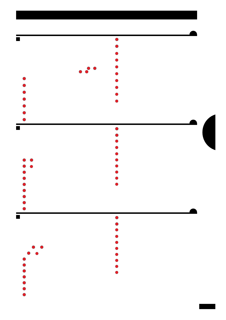
S
YStEmvErkaBElunG
Das Teilbreitenschaltsystem kann entweder durch Anschluss
beider Systeme an den gleichen Cobo-Stecker, oder mit
Y-Cobo Stecker (1 Stift und 2 Buchsenkontakte) oder über ei-
nen zweiten Cobo-Stecker des Schleppers mit Strom versorgt
werden.
Für den, auf der Seite des Schleppers gelegenen Teil sind das
die Nr.
1
bis
6
.
Für die auf der Machinenseite gelegenen Teile sind das die
Nr.
7
bis
17
.
1
Konsole VISION CAN - ECONOV
2
Teilbreitensteuerung (Smart boom)
3
Spurführung (Matrix Pro 840 GS)
4
GPS Antenne
5
ECONOV Steuerung
6
Verbindungskabel CAN
7
Verbindungsdose CAN
8
Steuerbordzylinder 3D
9
Zylinder zur linken Zuführung (Breite)
10
Zylinder zu rechten Zuführung (Breite)
11
Zylinder für die linke Streumenge
12
Zylinder für die rechte Streumenge
13
Sensor ILS linke Klappenöffnung
14
Sensor ILS rechte Klappenöffnung
15
Zylinder Stop & Go links (Klappenöffnung)
16
Zylinder Stop & Go rechts (Klappenöffnung)
17
Sensor der Wiegeeinrichtung
Steckdosenplan für den Smart Boom: (siehe Tabelle)
Im Automatikmodus ermöglicht durch die Zuführung von
12 V auf einen der Kontakte (1 bis 6) die Öffnung der ent-
sprechenden Teilbreite.
S
YStEm
wirinG
The boom section control system can either be powered by
connecting the two systems to the same cobo plug, or by
using a “Y” shaped cobo fitting (one male plug, two female
sockets), or alternatively by using a second cobo plug from
the tractor.
For the part located on the tractor side, these are from No.
1
to
6
.
For the part located on the machine side, these are from No.
7
to
17
.
1
VISION CAN - ECONOV console
2
Boom section management (Smart boom)
3
Guidance bar (Matrix Pro 840 GS)
4
GPS Antenna
5
ECONOV control unit
6
CAN intermediate wiring bundle
7
CAN Connection box
8
3D tribord actuator
9
Actuator for left-hand chute (width)
10
Actuator for right-hand chute (width)
11
Left-hand side rate actuator
12
Right-hand side rate actuator
13
Left shutter opening ILS sensor
14
Right shutter opening ILS sensor
15
Stop & Go left actuator (shutter opening)
16
Stop & Go right actuator (shutter opening)
17
Weighing sensor
Connector plan for the smart Boom: (see table)
In automatic mode, the supply of 12 volts on one of the
pins (1 to 6) allows the corresponding boom section to be
opened.
c
âBlaGE
du
SYStèmE
Le système de coupure de tronçons peut soit être alimenté
en branchant les deux systèmes sur la même prise cobo, soit
en utilisant un raccord cobo en « Y » (une prise mâle, deux
prises femelles), ou alors en utilisant une deuxième prise
cobo du tracteur.
Pour la partie située côté tracteur, ce sont les N°
1
à
6
.
Pour la partie côté machine ce sont les N°
7
à
17
.
1
Console VISION CAN - ECONOV
2
Gestion de tronçon (SMART BOOM)
3
Barre de guidage (MATRIX PRO 840 GS)
4
Antenne GPS
5
Commande ECONOV
6
Faisceau intermédiaire CAN
7
Boîte de connexion CAN
8
Vérin tribord 3D
9
Vérin de goulotte gauche (largeur)
10
Vérin de goulotte droit (largeur)
11
Vérin de débit gauche
12
Vérin de débit droit
13
Capteur ILS ouverture trappe gauche
14
Capteur ILS ouverture trappe droite
15
Vérin STOP & GO gauche (ouverture trappe)
16
Vérin STOP & GO droit (ouverture trappe)
17
Capteur de pesée
Le plan de la prise pour le SMART BOOM : (voir tableau)
En mode automatique l’envoi de 12 volts sur un des plots (1
à 6 ) permet l’ouverture du tronçon correspondant .
75
FR
GB
DE
Programmation / Programming / Programmierung
2
H
H
H