Omnitron Systems Technology iConverter 19-Module Chassis User Manual
Page 5
Page 5
This configuration provides the network administrator with the ability to provide multi-customer service using a single chassis
which is securely managed.
2.0
UNPACKING, VISUAL INSPECTION AND INVENTORY
Review the contents. The following items should be included:
iConverter 19-Module Power Chassis
2 Rack mounting “L” brackets and 12 screws
1, 2 or 3 power supplies depending on the model ordered:
8200-x or 8201-x (AC) / 8205-x or 8207-x (48VDC) / 8206-x (24VDC)
‘x’ indicates the number of power supplies installed
One power cord for each AC Power supply
User Manual
Inspect equipment and immediately report any damage or discrepancies to Omnitron at 949-250-6510. If equipment is damaged,
do not apply power to the equipment.
3.0
SITE PREPARATION AND INSTALLATION
3.1
Rack Mounting and Grounding the Chassis
Prepare the chassis for proper grounding to the office equipment.
The chassis is suitable for installation as part of the Common Bonding Network (CBN) per GR-1089-CORE, Issue 4 (sec 9.3).
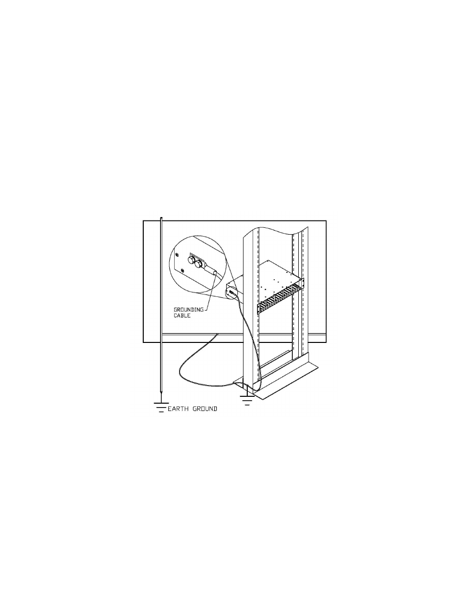
Verify the rack is properly grounded to Earth ground per Figure 4.
Fig. 4 Office Equipment Grounding
When rack mounting the chassis to a 19” standard rack, first attach the two enclosed “L” shaped rack mounting brackets to
the chassis using the enclosed screws.
Mount and attach the chassis (after the mounting brackets are installed) to the rack using the appropriate rack mounting
screws (not provided).
Clean and remove any paint and other nonconductive coatings from the chassis ground point and grounding lug surfaces.
Apply the appropriate antioxidant compound to the conductors.