4 application example – Omnitron Systems Technology iConverter 19-Module Chassis User Manual
Page 4
Page 4
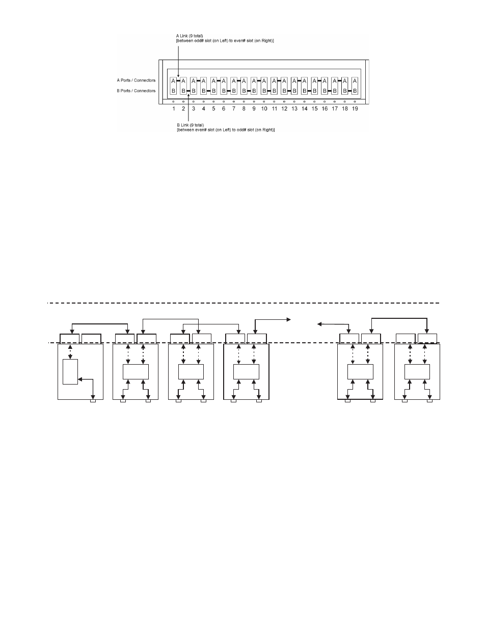
Fig. 2 19-Module Backplane Architecture
Fig. 2 depicts the chassis’ backplane architecture including the A and B Links.
The A Links connect between odd numbered slots on the left to even numbered slots on the right (i.e. 1-2, 3-4, 5-6, 7-8, 9-10,
11-12, 13-14, 15-16, 17-18).
The B Links connect between even numbered slots on the left to odd numbered slots on the right (i.e. 2-3, 4-5, 6-7, 8-9, 10-11,
12-13, 14-15, 16-17, 18-19).
When modules with A and B Port capabilities are inserted into adjacent chassis slots, they can connect to each other via the
backplane links and create flexible network architectures that meet the user’s requirements.
NOTE: Not all modules support and have backplane ports. To find out about each specific module’s backplane port
configuration, refer to the specific module’s documentation.
This chassis architecture facilitates a variety of applications including unmanaged, out-of-band managed, in-band managed and
multi-port configurations.
1.4
Application Example
Fig. 3 depicts an out-of-band managed 10/100 converter application. In this application which is typical for a Central Office (CO)
or a network core, a 19-Module chassis is loaded with 10/100 UTP to fiber converters that convert UTP cabling originating at a
core switch to fiber and distributing the fiber in a star configuration to different customers.
“B” Link to slot 4
“A” Link to slot 17
“A” Link
“B” Link
“B” Link
Chassis
Backplane
10/100 Module
10/100 Module
10/100 Module
Internal
10/100
switch chip
Internal
10/100
switch chip
Internal
10/100
switch chip
UTP
10/100 port
UTP
10/100 port
UTP
10/100 port
Fiber
100 port
Fiber
100 port
Fiber
100 port
NMM2 Module
A Port
B Port
A Port
B Port
A Port
B Port
A Port
B Port
Slot 1
Slot 2
Slot 3
Slot 4
NMM2
NMM2 UTP
100 port
“A” Link
10/100 Module
10/100 Module
Internal
10/100
switch chip
Internal
10/100
switch chip
UTP
10/100 port
UTP
10/100 port
Fiber
100 port
Fiber
100 port
A Port
B Port
A Port
B Port
Slot 18
Slot 19
Fig. 3 Out-of-Band Managed 10/100Mbps Converter Application
Out-of-band management is desirable in this application since it facilitates secure monitoring, configuration and trap notification
of a large number of converter modules in the chassis.
This application uses eighteen 10/100 modules for UTP to fiber conversion and a Network Management Module (NMM2) for
management. All modules are plugged into the 19-Module chassis.
The 10/100 converter module is designed as a 4-port switch with two Ethernet front panel ports (100BASE-FX fiber and
10/100BASE-T/TX UTP) and two 10/100 Ethernet backplane ports (A and B Ports). In this application, the A and B Ports are
disabled to provide isolation between the modules.
The NMM2 features a 100Mbps Ethernet A Port. In this application, its A port is disabled and connectivity to the management
network is performed via the front panel Ethernet port on the NMM2.
It is important to emphasize that in this type of application, the A and B Ports of all of the 10/100 converters must be disabled to
facilitate user data privacy by isolating the converters from each other and from the A and B Links.
It should also be noted that in this configuration, in addition to data privacy infringement, enabling the A and B Links will cause
a broadcast storm (since the modules create closed loops through the switch) or partitioning of some of the data paths by the
switch.
The management data flows between the NMM2 front panel (out-of-band) and the network management hardware.