MTS 318 Load Unit User Manual
Page 89
Routine Maintenance Overview Checklist
318 Load Unit
Maintenance
89
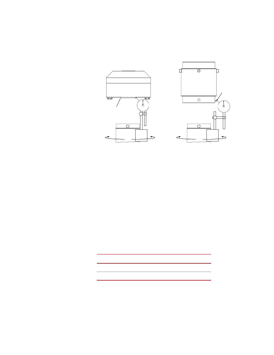
3. Check the alignment.
In this step, you check the alignment between the force transducer and the
actuator.
.
Attaching and Zeroing the Indicator
A. Attach the dial indicator to the actuator.
On a low profile force transducer, adjust the indicator to take the
reading along the edge of the loading surface.
On cylindrical style force transducers, adjust the indicator so that its
stylus just touches the polished bottom edge of the transducer.
B. Zero the indicator.
C. Slowly turn the actuator to rotate the indicator 360
° around the force
transducer.
Stop frequently to take indicator readings. Keep your hands off the
actuator and indicator when taking the readings. Compute the total
indicator runout (TIR). Take the maximum dial indicator reading and
subtract the minimum dial indicator reading.
D. If the TIR is 0.038 mm (0.0015 in) or less, the force transducer is
accurately aligned with the actuator. Go to Step 6.
If the TIR is greater than 0.038 mm (0.0015 in), the force transducer
needs to be aligned with the actuator. Start over with Step 3.
L
OAD
U
NIT
R
ATING
TIR
250 kN (55 kip) or less
>0.038 mm (0.0015 in)
500 kN (100 kip)
0.051 mm (0.0020 in)
360°
360°
Read
along
the edge
Read
along
the edge
Zero
Zero