Marshalltown SP684 SURFACE SHARK Surface Planer User Manual
Page 31
SP684 SuRFACE ShARK SuRFACE PLANER
PAGE 31
Observe all applicable safety precautions for the
solvent.
3) using a 1/2 inch wrench, remove the self locking
nuts on the engine/electric motor take-up cap screws.
Rotate the take-up capscrews until the hexagon head
contacts the threaded mounting plate.
4) using the 1/2 inch wrenches, loosen the engine/
electric motor attachment cap screws, and slide the
engine/electric motor toward the front of the main
frame. FIGuRE 30.
FIGuRE 30
5) Remove the worn belt and install the replacement
v-belt, Part# M3vX335.
a) Do not install a replacement belt if the pulleys
have worn grooves. Such pulleys should be replaced
to insure proper belt fit. operating the v-belt in
worn pulley grooves will accelerate v-belt wear and
significantly reduce its service life.
b) A v-belt should never be forced over a pulley. More
belts are broken from this cause than from actual
failure in service.
c) Keep the belt as clean and free of foreign material
as possible. Do not use belt dressing.
6) Reinstall the engine/electric motor take-up cap
screws with the heads facing toward and in contact
with the engine crankcase/electric motor thrust plate.
Tighten the engine/electric motor attachment cap
screws until they just begin to apply tension to the
engine/electric motor. Do NoT ovER TIGhTEN.
Alternately tighten the take-up cap screws until slight
tension is applied to the v-belt.
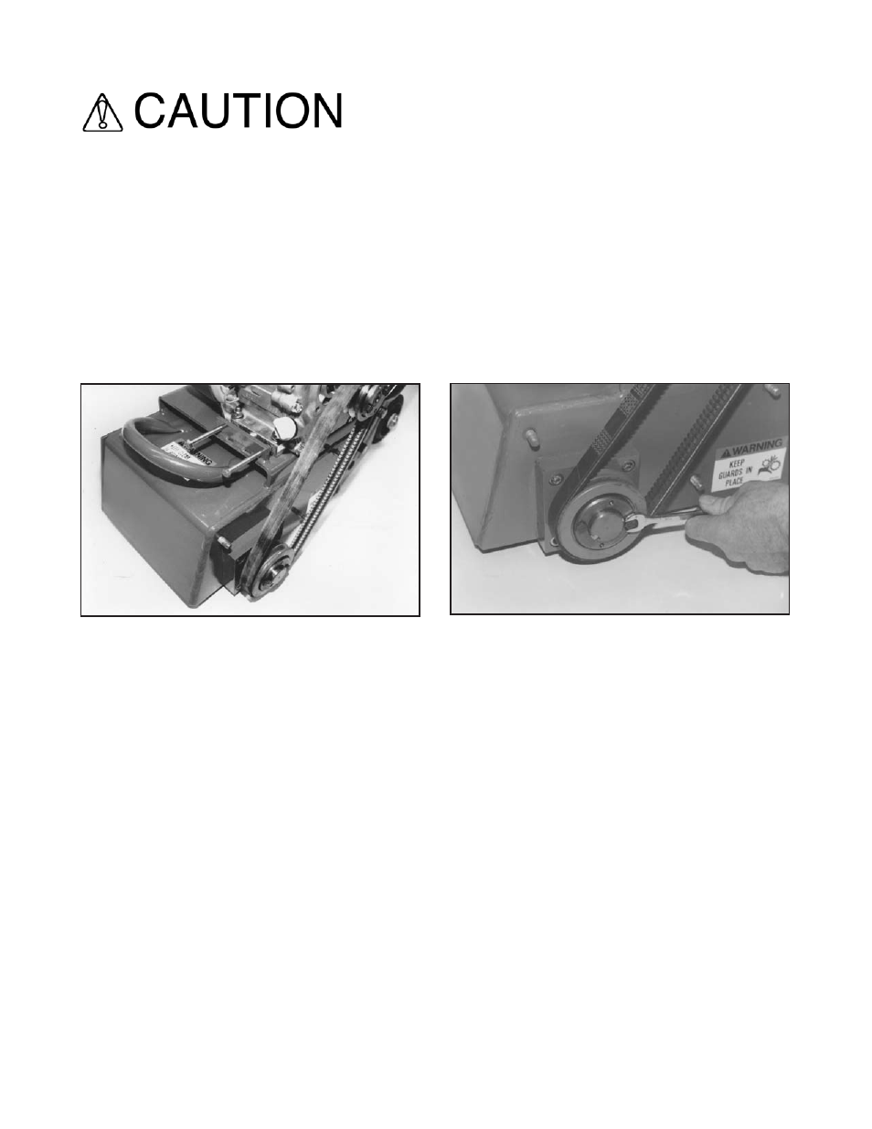
7) The driveshaft pulley should be positioned within
1/16 inch if the shaft shoulder. If the distance exceeds
this limit, proceed as follows:
a) using the 7/16 inch wrench, remove the two 1/4 inch
diameter cap screws from the bushing.
b) Insert the cap screws into the tapped holes in the
bushing flange. Tighten progressively until the bushing
disengages from the pulley.
c) Insert the 1/4 inch diameter cap screws into the
tapped holes in the pulley. Tighten progressively until
the bushing applies tension to the pulley. FIGuRE 31.
FIGuRE 31
d) Tap the pulley/bushing assembly against the shaft
shoulder with the soft hammer.
e) Tighten the 1/4 inch diameter cap screws
progressively with a torque wrench to 95 inch pounds.
Note: this installation procedure is also used when
installing replacement pulleys.
8) belt alignment is checked with the straightedge.
Place the straightedge squarely against the driveshaft
pulley. Properly aligned pulleys should also place
the straightedge squarely against the engine/electric
motor pulley. Remove the straightedge and rotate the
engine pulley 120 degrees. Recheck the alignment
with the straightedge. Repeat the process until the
engine/electric motor pulley has been rotated a full 360
degrees. Maximum allowable misalignment is +- 1/32
inch. FIGuRE 32.