Marshalltown SP684 SURFACE SHARK Surface Planer User Manual
Page 21
SP684 SuRFACE ShARK SuRFACE PLANER
PAGE 21
FIGuRE 18
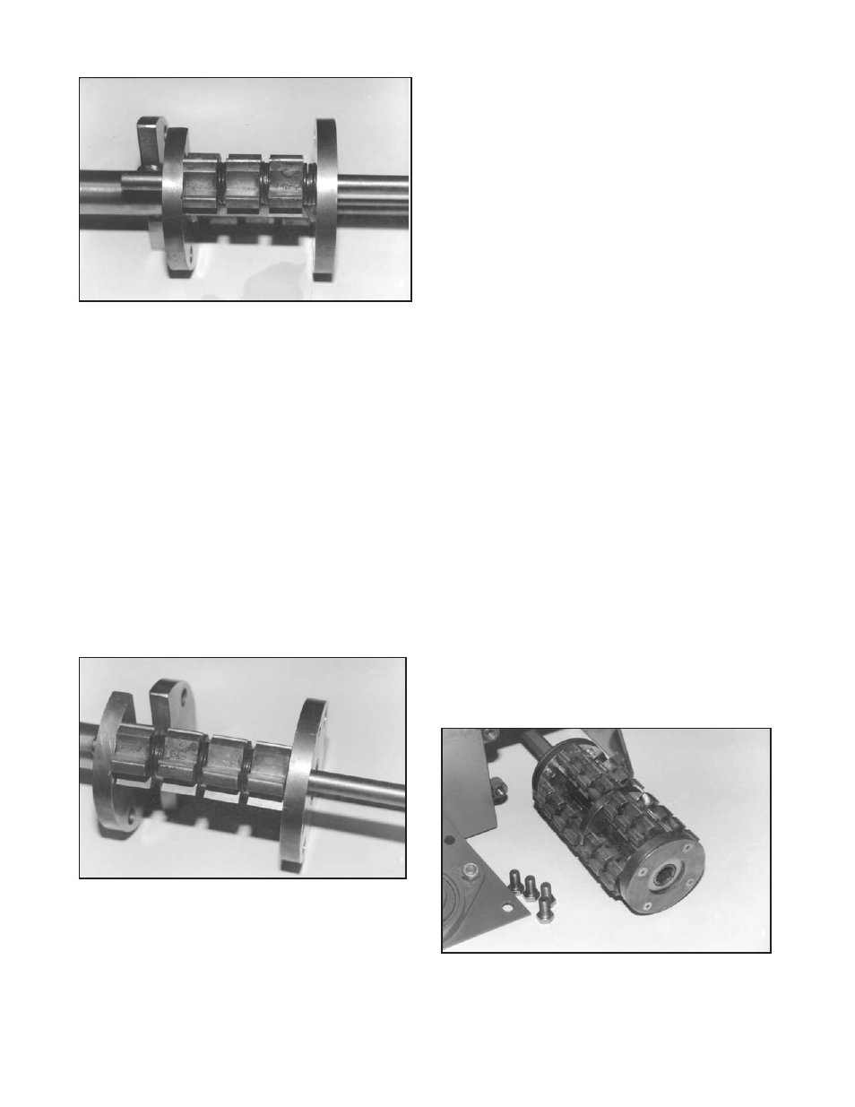
2) Install a flail next to the outside side plate of the wide
section. Next, install two spacer washers. Follow with a
flail and two spacer washers. Install another milling flail
followed by three spacer washers. Finally, install the
remaining flail and one spacer washer. The tungsten
carbide inserts must be installed to form the same,
continuous planing surface as in Step 1. FIGuRE 19.
3) Milling flails can also be installed on the drum
without the use of spacer washers.
General Notes Regarding the Installation of Flails:
1) because of variance in material thicknesses and
manufacturing tolerances, the specified number of
spacer washers may not always fit within the narrow
and wide sections. If this occurs, grinding a spacer
washer to reduce its thickness is an option.
FIGuRE 19
Exercise caution when grinding a spacer washer to
reduce its thickness. Wear safety eye wear and other,
appropriate safety apparel to minimize the potential for
personal injury.
2) Flails require sufficient free play to allow them to
properly impact the work surface material. If the flails
fit too tight on the drum, inconsistent material removal
and accelerated flail wear will result. The formation of
rust between the flail and spacer washer surfaces will
affect proper free play. Excessive free play can also
accelerate the wear of flails and rods. As a general
rule, flails should be free to rotate by hand after
being installed on the drum. If this is not possible,
the flails should be disassembled and additional free
play provided by reducing the thickness of a spacer
washer.
3) All flails are bi-directional in design with the exception
of the milling flail. That is, there is no forward or reverse
orientation on the drum. Fail service life can sometimes
be extended by reversing their orientation on the
driveshaft. The effect is similar to rotating tires on an
automobile.
4) As the name implies, the tungsten carbide inserts
of the milling flail cut the work surface material with an
action very similar to that of a machine tool cutting steel.
The brittleness of the tungsten carbide insert requires
that it be fully supported to minimize breakage. This
requires a substantial flail body to provide the necessary
support. The resulting configuration makes the milling
flail one directional in design. This limitation requires
the operator to install a loaded drum on the driveshaft
with the tungsten carbide inserts facing the direction
of rotation. FIGuRE 20. If the tungsten carbide inserts
face opposite to the direction of rotation, improper
milling action and accelerated flail wear will occur.
FIGuRE 20