2 assignment of the control terminals, Assignment of the control terminals, Installation – Lenze 8240 frequency inverters User Manual
Page 28
Installation
4-12
UOOu_^MTMO
L
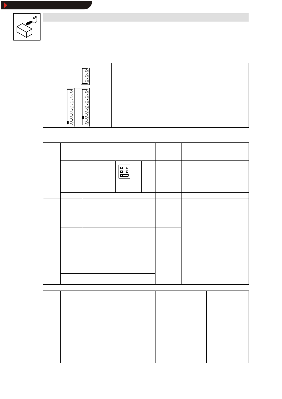
4.2.3.2
Assignment of the control terminals
62
7
8
9
K11
K12
K14
20
28
E1
E2
E3
E4
39
K21
K22
K24
Protection against contact
The control terminals have a basic isolation (double insulating distance). The protection
against contact is ensured without any additional measures.
Protection against polarity reversal
The protection against polarity reversal prevents the wrong connection of the internal
control inputs. It is however possible to overcome the protection against polarity reversal
by applying great force.
Motor-temperature monitoring
The connections of the motor-temperature monitoring (T1, T2) are next to the connection
terminals U, V, W.
cfd QJV
mçëáíáçå зС нЬЙ Езенкзд нЙкгбе~дл
Terminal
Use
(Factory setting is printed in bold)
Level
Data
Analog
7
GND 1
g
inputs
8
Setpoint input,
reference:
Terminal 7
(0 to 10V)
6
4
2
5
3
1
5 - 6
5 - 6
3 - 4
1 - 2
0 to 20 mA
4 to 20 mA
0 to 5 V
0 to 10 V
Resolution: 10 bit
Linearity fault:
±0.5 %
Temperature fault: 0.3 % (0...+40
°C)
Input resistance
Voltage signal: > 100 kΩ
Jumper
Voltage signal: > 100 kΩ
Current signal: 250 Ω
9
Supply for setpoint potentiometer
5.2V / 6mA
Analog
output
62
Analog output, reference: terminal 7
(Field frequency)
0... 6 V / 2 mA Resolution: 10 bit
Digital
inputs
20
Voltage supply for digital inputs
15 V/20 mA
p
28
Controller enable
HIGH
HIGH:
12 V ... 30 V
E4
CW rotation/
CCW rotation (CW/CCW)
CW: LOW
CCW: HIGH
LOW:
0 V ... 3 V
E3
DC-injection brake
HIGH
E2
JOG frequencies
Binary code
E1
q
20Hz, 30Hz, 40Hz
y
39
GND 2 (reference for external voltages)
Monitoring T1
Motor-temperature monitoring
(PTC thermistor/thermal contact)
If not used: set parameter C119 = -0-!
T2
Motor-temperature monitoring
(PTC thermistor/thermal contact)
Terminal
Use
(Factory setting is printed in bold)
Relay position (switched)
Data
Relay
output K1
K 11
Relay output normally-closed contact
(TRIP)
opened
24 V AC / 3,0 A or
60 V DC / 0.5 A
p
K 12
Relay mid-position contact
K 14
Relay output normally-open contact
(TRIP)
closed
Relay
output K2
K 21
Relay output normally-closed contact
(Ready for operation)
opened
250 V AC / 3,0A or
60 V DC / 0.5A
p
K 22
Relay mid-position contact
250 V AC / 3,0A or
60 V DC / 0.5A
K 24
Relay output normally-open contact
(Ready for operation)
closed
250 V AC / 3,0A or
60 V DC / 0.5A
Show/Hide Bookmarks