Operation – Lenze S94P01G Position Servo User Manual
Page 63
S94P01G
61
Operation
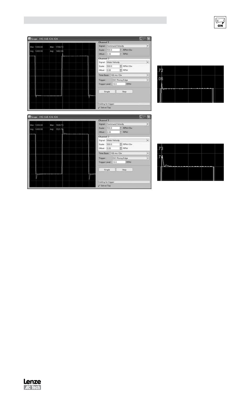
I-Gain set OK
No error between Commanded steady state
velocity and Actual steady state velocity with
excellent stability.
I-Gain set too HIGH
Additional overshoot and oscillations are
starting to occur. Steady state velocity
regulation
Step 4: Check Motor Currents
Finally check the motor currents on the Oscilloscope. Make the following settings to the
oscilloscope.
Channel 1:
Signal
= “Phase Current RMS”
Scale
= as appropriate to peak current limit set in drive parameters (MotionView)
Timebase: = as appropriate to “Period” value of Indexer Program
Trigger:
= Channel 2, Rising Edge
Level:
= 10 RPM
Observe the waveforms to insure there are no significant oscillations. Reduce the gains
values if necessary.
The current waveform should be showing spikes of current during acceleration /
deceleration and steady state current during any steady state velocity. The maximum
value (peak value) of the current waveform is shown at the top of the oscilloscope
screen. This maximum value can be compared to the drive nominal current and peak
current settings to check how much of the motors potential performance is being used
and if optimum performance is being achieved.