Interface – Lenze S94P01G Position Servo User Manual
Page 25
S94P01G
23
Interface
4.1.7 Connector and Wiring Notes
Note 1 - Buffered Encoder Inputs
Each of the encoder output pins on P3 is a buffered pass-through of the corresponding
input signal on P4, Refer to section 4.2.2 “Buffered Encoder Outputs”. This can be
either from a motor mounted encoder/resolver, (primary feedback), or from an auxiliary
encoder/resolver when an optional feedback module is used.
Via software, these pins can be re-programmed to be a buffered pass through of the
signals from a feedback option card. This can be either the second encoder option
module (E94ZAENC1) or an encoder emulation of the resolver connected to the resolver
option module (E94ZARSV2 or E94ZARSV3).
Note 2 - Master Encoder Inputs or Step/Direction Inputs
An external pulse train signal (“step”) supplied by an external device, such as a PLC or
stepper indexer, can control the speed and position of the servomotor. The speed of the
motor is controlled by the frequency of the “step” signal, while the number of pulses that
are supplied to the PositionServo determines the position of the servomotor. Direction
input controls direction of the motion.
Note 3 - Digital Input A3
For the drive to function, an ENABLE input must be wired to the drive, and should be
connected to IN_A3, (P3.29), which is, by the default the ENABLE input on the drive.
This triggering mechanism can either be a switch or an input from an external PLC or
motion controller. The input can be wired either sinking or sourcing (section 4.2.3). The
Enable circuit will accept 5-24V control voltage.
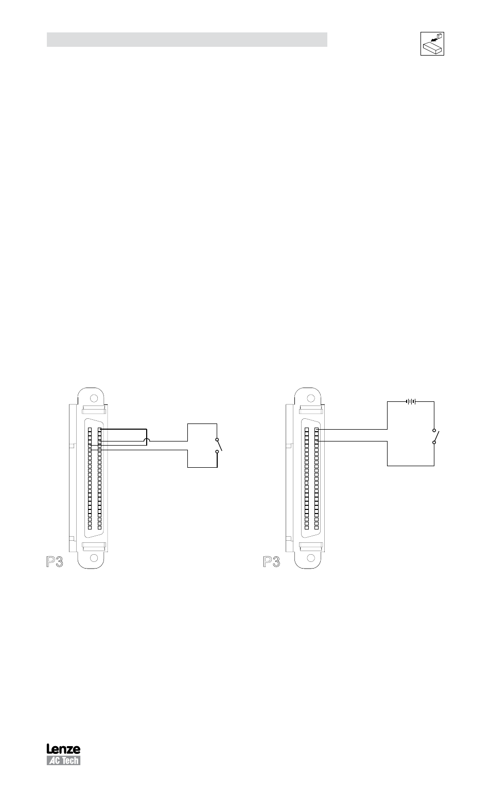
Wiring the Enable Input:
Pin 6 +5V
P n 5 GND
Pin 26 IN A COM
Pin 29 N A3
CONTROLLER
/O
1
25
P3
50
26
Power Supply
Pin 26 IN A COM
Pin 29 IN A3
+
CONTROLLER
/O
1
25
P3
50
26