Electrical installation, Resolver connection – Lenze MDSLS Servo spindle motor User Manual
Page 25
Electrical installation
Important notes
Wiring diagrams for servo spindle motors MDSLS
5
25
BA 33.0003 EN 1.0
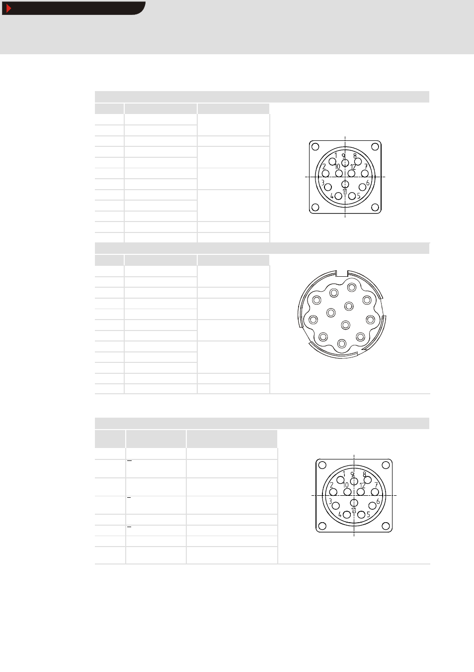
Resolver connection
Lenze connector - standard (RS1)
Pin no.
Terminal designation
Meaning
1
+ Ref
Transformer windings
( f
i di
)
2
- Ref
g
(reference windings)
3
Not assigned
4
+ Cos
Stator windings
C i
5
- Cos
g
Cosine
6
+ Sin
Stator windings
Si
7
- Sin
g
Sine
8
Not assigned
9
g
10
hPPKMMNULP
11
+ KTY
Thermal detector +
hPPKMMNULP
12
- KTY
Thermal detector -
Connector KUKA - compatible (RS3)
Pin no.
Terminal designation
Connection to:
10
+ Ref
Transformer windings
7
- Ref
Transformer windings
(reference windings)
8
3
Not assigned
1
7
8
9
11
+ Cos
Stator windings Cosine
1
7
9
10
12
12
- Cos
Stator windings Cosine
2
6
10
11
12
1
+ Sin
Stator windings
3
5
11
2
- Sin
Stator windings
Sine
3
44
5
4
44
5
Not assigned
6
Not assigned
View from “outside”
8
+ KTY
Thermal detector +
View from outside
9
- KTY
Thermal detector -
Connection of incremental value encoder / SinCos absolute value encoder
Connector
Pin no.
Terminal
designation
Meaning
1
B
Track B / + SIN
2
3
A
A
Track A inverse / - COS
Track A / + COS
4
5
+ 5 V
GND
Supply + 5 V / + 8 V
Ground
6
7
Z
Z
Zero track inverse / - RS485
Zero track / + RS485
8
Not assigned
9
B
Track B inverse / - SIN
10
Not assigned
° d d
11
12
+ KTY
- KTY
Thermal detector +
Thermal detector -
20° coded
Show/Hide Bookmarks