1 emc-compliant wiring, 2 wiring diagrams for servo spindlemotors mdsls, Emc-compliant wiring – Lenze MDSLS Servo spindle motor User Manual
Page 24: Wiring diagrams for servo spindle motors mdsls, Electrical installation, Stop
Electrical installation
Important notes
Wiring diagrams for servo spindle motors MDSLS
5
24
BA 33.0003 EN 1.0
5.1.1
EMC-compliant wiring
TheEMC-compliantwiringofthemotorsisdescribedindetailinthe operatinginstructions
of the Lenze servo inverters 9300 and ECS.
ƒ Use of EMC threaded joints made out of metal with shield connection.
ƒ Shield connection at the motor and at the device.
5.1.2
Wiring diagrams for servo spindle motors MDSLS
Stop!
ƒ
Securely tighten the nut of the connector.
ƒ
In case of vibration stress, secure with an O-ring:
–
Power terminal MDSLS:
O-ring 18 x 1.5 mm
–
Encoder connection:
O-ring 18 x 1.5 mm
–
Never pull the plug if the machine is active! The plug could be destroyed!
Inhibit the controller before pulling the plug!
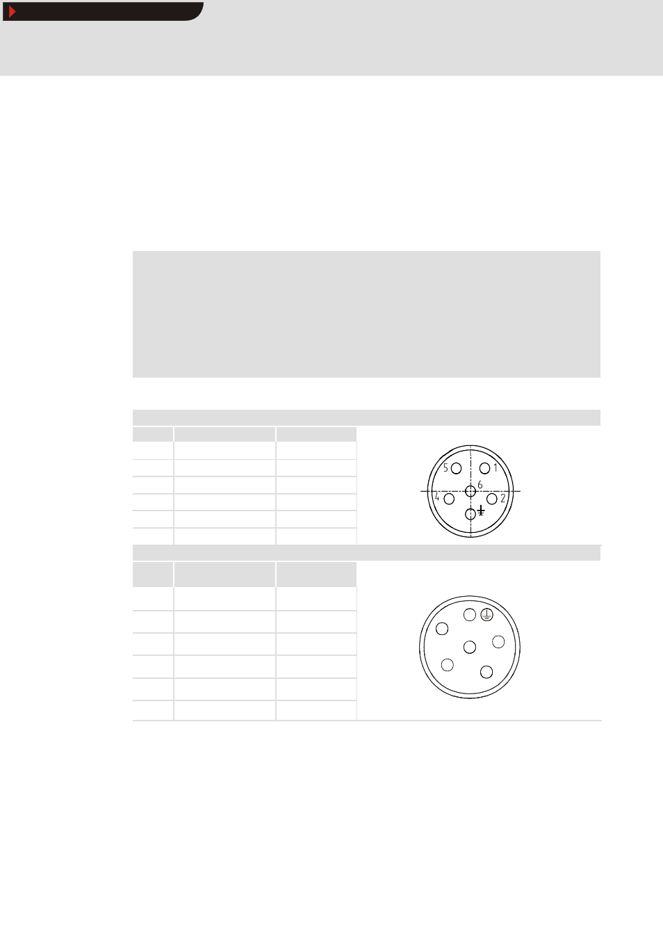
Power terminal of servo spindle motors MDSLS 056 and 071
Lenze connector - standard
Pin no.
Terminal designation
Meaning
1
Y1 / BD1
Holding brake +
2
Y2 / BD2
Holding brake -
PE
PE
PE connector
4
U
Power phase U
5
V
Power phase V
6
W
Power phase W
KUKA connector- compatible
Pin no.
Stranded wire colour in
the box
Connection to:
4
red
Holding brake +
5
blue
Holding brake -
PE
green-yellow
PE connector
2
4
1
red
Power phase U
6
2
blue
Power phase V
1
5
6
black
Power phase W
View from “outside”
Show/Hide Bookmarks