Electrical installation – Lenze 931W User Manual
Page 17
Electrical installation
Electrical connection of the servo inverter with the PROFIBUS master
4
17
K-HB 13.0001-EN
2.1
4.1
Electrical connection of the servo inverter with the PROFIBUS master
To meet the requirements of the enclosure IP 54, the servo inverter is equipped with screw
connectors with M12 threads.
The connection plan and assignment of the power connector of the devices can be
obtained from the Operating Instructions 931 M / W.
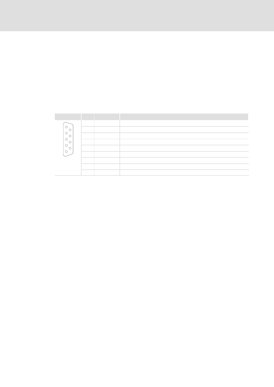
The following shows the assignment of a 9-pole Sub-D socket the most PROFIBUS masters
are equipped with for connecting field devices.
Connection of the PROFIBUS to 9-pole SubD socket
View
Pin
Designation Explanation
1
6
2
7
3
8
4
9
5
1
free
—
2
free
—
3
RxD/TxD-P
Data line B (Receive / transmit data plus)
4
RTS
Request To Send (receive / transmit data, no differential signal)
5
M5V2
Data ground (5 V)
6
P5V2
DC 5 V / 30 mA (bus termination)
7
free
—
8
RxD/TxD-N
Data line-A (receive / transmit data minus)
9
free
—
Tab. 2
Sub-D connection PROFIBUS