Parameter setting, Show/hide bookmarks – Lenze EMF2112IB User Manual
Page 35
Parameter setting
6-13
BA2112EN
Controllers 82XX and 8200 vector (C0001 = 3) and 93XX
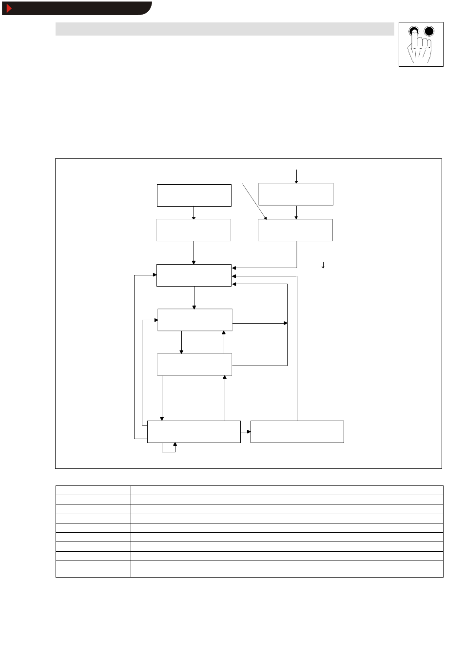
With INTERBUS-DP control (82XX: Lenze parameter C0001 = 3; 93XX: always) and when using the
2112 fieldbus module, the Lenze controller status is normalized according to the DRIVECOM-Profile
20.
Information about the current unit status (Fig. 6-4 rectangles in the status diagram) are available in
the DRIVECOM parameter “ Status word“ . Commands in the DRIVECOM parameter control word
can change the controller status. These commands are marked by arrows in the following diagram.
Inhibit voltage
xxxx xxxx xxxx xx0x
automatically, if the error reaction is over
Standstill
xxxx xxxx
xxxx x110
Standstill
xxxx xxxx xxxx
x110
Switch on
xxxx xxxx
xxxx x111
automatically when
initializing is completed
Reset fault
xxxx xxxx 0xxx xxxx
Switch on unit
Status word xxxx xxxx x0xx 0000
NOT READY TO SWITCH ON
READY TO SWITCH ON
Status word xxxx xxxx x01x 0001
SWITCHED ON
Status word xxxx xxxx x01x 0011
OPERATION ENABLED
Status word xxxx xxxx x01x 0111
Fault
Status word xxxx xxxx x0xx 1000
Example:
Status information by means of
„status word“
Bit 15 ... bit 0 (binary display)
SWITCH ON INHIBIT
Status word xxxx xxxx x0xx 0000
QUICK STOP ACTIVE
Status word xxxx xxxx x01x 0111
Operation enable
xxxx xxxx xxxx 1111 and
act. speed value
≠
0*
Operation inhibit
xxxx xxxx xxxx 0111 or act.
speed value = 0*
Inhibit RFG is mapped to
quick stop
Quick stop
xxxx xxxx xxxx x01x
Quick stop
xxxx xxxx xxxx x01x
Inhibit voltage
xxxx xxxx xxxx xx0x
Standstill
xxxx xxxx xxxx x110
FAULT REACTION ACTIVE
Status word xxxx xxxx x0xx 1111
Malfunction was recognized
xxxx xxxx 1xxx xxxx
Inhibit voltage
xxxx xxxx xxxx xx01
or
quick stop completed
9
8
4
5
11
6
7
10
12
14
13
3
Note:
* only valid for 821X, 8200 vector when the automatic
DC-injection brake is active (C0106, C2106
≠
0)
2
Fig. 6-4
Status diagram DRIVECOM unit control
Status
Meaning
NOT READY TO SWITCH ON
The controller is being initialized and is not yet ready to operate. It then automatically switches to the status READY TO SWITCH ON.
SWITCH ON INHIBIT
The controller is inhibited and waits for command 2 (shut down).
READY TO SWITCH ON
The controller is inhibited and waits for command 3 (switch on).
SWITCHED ON
The controller is inhibited and waits for command 4 (enable operation).
OPERATION ENABLED
The controller is enabled. In this status, a pulse inhibit can be set automatically.
FAULT REACTION ACTIVE
A fault (TRIP) was recognized and a fault response initiated.
FAULT
The controller is in the status “FAULT“ (TRIP).
QUICK STOP ACTIVE
While being in the status “OPERATION ENABLED“ the command “Quick stop“ was set. The controller is decelerated in a controlled
way (quick-stop ramp). After deceleration, the controller automatically changes to the controller status “SWITCH ON INHIBIT“.
The actual unit status can only be clarified by combining the unit-status information bits (bit 0 to 6).
This is shown in the following:
Show/Hide Bookmarks