4 installation, 1 connections of the fieldbus module 2112, Connections of the fieldbus module 2112 – Lenze EMF2112IB User Manual
Page 13: Installation, 4installation
Installation
4-1
BA2112EN
4
Installation
4.1
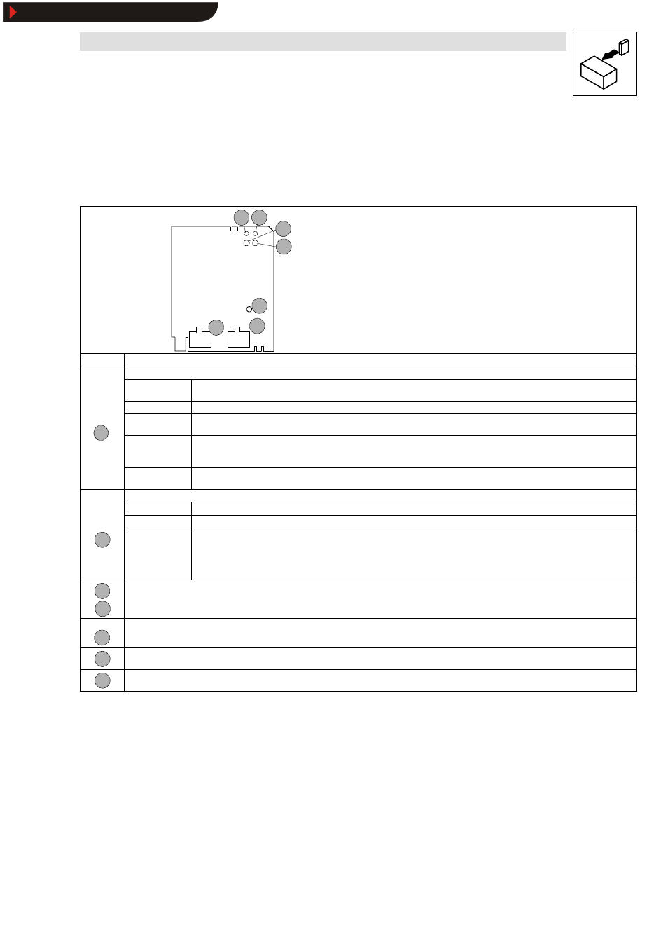
Connections of the fieldbus module 2112
INTERBUS loop
2112
IN
OUT
5
4
3
2
1
7
6
Fig. 4-1
Name/meaning of the module elements
No.
Name/Meaning
Yellow bus LED
Status: Bus communication
ON
Fieldbus module 2112 has been initialized
INTERBUS communication with the master is possible.
OFF
Fieldbus module 2112 is not supplied with voltage yet.
1
BLINKING
(4 Hz)
Peripheral fault/open circuit
Voltage supply from the INTERBUS-Loop, but no INTERBUS communication.
1
BLINKING
(2 Hz)
Voltage supply if INTERBUS communication is active. Error telegrams caused by, e.g. open circuit, are generated.
•
Module not connected to the controller or
•
initialization active.
BLINKING
(0.5 Hz)
Voltage supply (5 V) from INTERBUS-Loop, but no INTERBUS communication.
Green LED
ON
2112 fieldbus module is supplied with voltage and is connected to the controller.
OFF
The 2112 fieldbus module is supplied via INTERBUS-Loop.X
2
BLINKING
2112 fieldbus module is supplied with voltage but is not connected to the controller.
Controller is
•
switched-off,
•
being initialized or
•
not available
4
3
Green LED or red LED
Operating status of the controllers 82XX, 8200 vector and 93XX. (See Operating Instructions for the controller)
5
Fixing screw for fieldbus module
6
INTERBUS-Loop input (IN)
7
INTERBUS-Loop output (OUT)
Show/Hide Bookmarks