2 process-data assignments for 82xx, Process-data assignments for 82xx, Parameter setting – Lenze EMF2112IB User Manual
Page 24
Parameter setting
6-2
BA2112EN
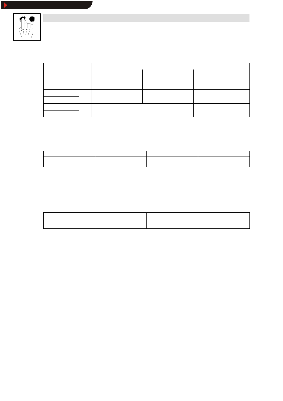
Assignment of process input data words
Meaning for
Byte No.
Unit control
C0009 = 11
DRIVECOM control
C0009
≠
11, 12
User defined
control profile
C0009 = 12
(only 8200 vector / 93XX)
1 HIGH byte; bit 8-15
PIW1
DRIVECOM stat s word
DRIVECOM stat s word
Link: W1 to AIF-OUT
2 LOW byte; bit 0-7
PIW1
DRIVECOM status word
DRIVECOM status word
Link: W1 to AIF-OUT
1 HIGH byte; bit 8-15
PIW2
82XX / 8200 vector:
Actual speed
Link: W2 to AIF-OUT
2 LOW byte; bit 0-7
PIW2
82XX / 8200 vector:
Actual speed
93XX:
Freely configurable
Link: W2 to AIF-OUT
6.1.1.2
Process-data assignments for 82XX
Structure of the PO-data response (data to drive)
Byte 1
Byte 2
Byte 3
Byte 4
Control word
High byte
Control word
Low byte
Setpoint
High byte
Setpoint
Low byte
Control word: see chapter 6.1.3.2
Setpoint: frequency setpoint
Here the frequency setpoint is preselected as process data word. The normalization is here
indicated as signed value with
б
24000 =
б
480 Hz.
Structure of the PI data response (data from drive)
Byte 1
Byte 2
Byte 3
Byte 4
Status word
High byte
Status word
Low byte
Actual value
High byte
Actual value
Low byte
Status word: see chapter 6.1.3.3.
Actual value: act. frequency value
The actual frequency value is provided as signed normalization
б
24000 =
б
480 Hz.
Show/Hide Bookmarks