1 power connections, 3 holding brake dc 24 v (optional), Power connections – Lenze MDFQA Operating Instructions User Manual
Page 33: Holding brake dc 24 v (optional), Electrical installation, Terminal box cable glands for the fan terminal box, En 33, Cable glands for the fan terminal box
Electrical installation
Terminal box
Cable glands for the fan terminal box
EN
33
Lenze ¯ BA 33.0006 ¯ 3.0
Cable glands for the fan terminal box
Motor type/size
Screwed connection
MCA/MQA
20
1 x M 16 x 1.5
22
26
6.4.1
Power connections
MCA; MCS, MQA 20...22, MD
LKS, SDSGA, SDSGS
Terminal
Standard description
Meaning
+
PE
PE conductor
U
V
W
U
V
W
Motor winding phase U
Motor winding phase V
Motor winding phase W
TP1
TP2
TP1
TP2
PTC thermistor
TB1
TB2
TB1
TB2
Thermostat
Thermal NC contact
MCA 26, MQA 26, MDFQA 160
Terminal
Standard description
Meaning
+
PE
PE conductor
1
2
3
U1
V1
W1
Start of winding phase U
Start of winding phase V
Start of winding phase W
4
5
6
W2
U2
V2
End of winding phase W
End of winding phase U
End of winding phase V
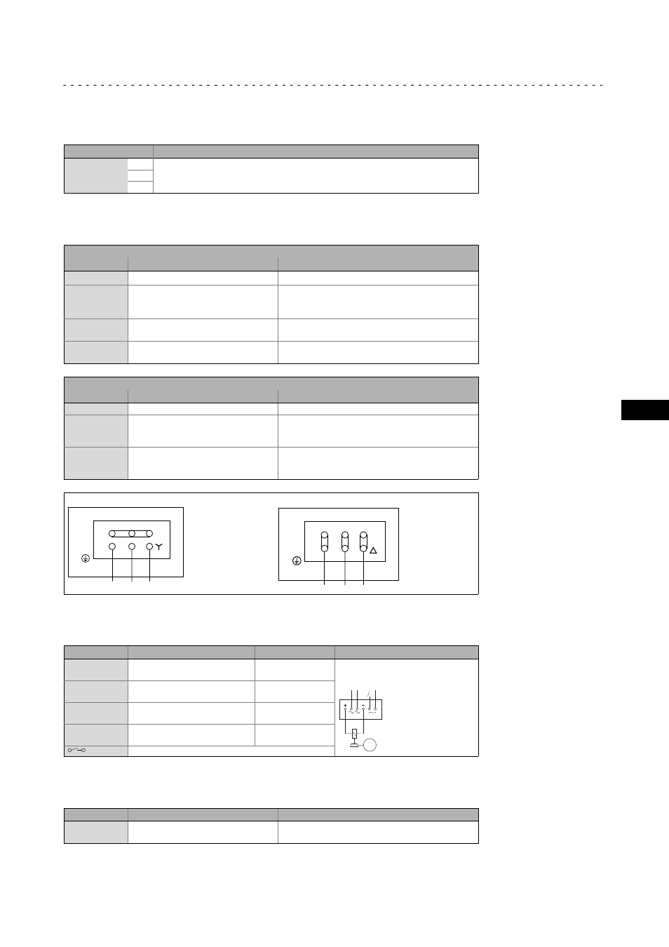
Star connection
Delta connection
L1 L2 L3
PE
(W1)
(U1) (V1)
(W2) (U2) (V2)
1
2
3
4
5
6
L1 L2 L3
PE
(W1)
(U1) (V1)
(W2) (U2) (V2)
1
2
3
4
5
6
6.4.2
Holding brake DC 205 V − connected via rectifier (optionl)
Terminal
Standard description
Meaning
~
BA1
Connection to L1 −
mains
AC−excited brake (rectifier)
~
BA2
Connection to N −
mains
M
3~
L1 N
+
BD1 (factory−set wiring)
Connection of
holding brake +
−
BD2 (factory−set wiring)
Connection of
holding brake −
Switching contact, DC switching
6.4.3
Holding brake DC 24 V (optional)
Terminal
Standard description
Meaning
BD1
BD2
BD1
BD2
Holding brake +
Holding brake −