2 wiring according to emc, 3 plug connectors, 1 power connections / holding brake – Lenze MDFQA Operating Instructions User Manual
Page 29: Wiring according to emc, Plug connectors, Power connections / holding brake, Electrical installation
Electrical installation
Wiring according to EMC
EN
29
Lenze ¯ BA 33.0006 ¯ 3.0
6.2
Wiring according to EMC
The EMC−compliant wiring of the motors is described in detail in the Operating
Instructions for the Lenze controllers.
¯
Use of metal EMC cable glands with shield connection.
¯
Connect the shielding to the motor and to the device.
6.3
Plug connectors
(
Stop!
¯ Tighten the coupling ring of the connector.
¯ If plugs without SpeedTec bayonet nut connectors are used, the
connector boxes for the power / encoder / fan connections must be
secured by O−rings if loadings by vibration occur:
– M17 connector box with O−ring 15 x 1.3 mm
– M23 connector box with O−ring 18 x 1.5 mm
– M40 connector box with O−ring 27 x 4.0 mm
¯ Never disconnect plugs when voltage is being applied! Otherwise, the
plugs could be destroyed! Inhibit the controller before disconnecting
the plugs!
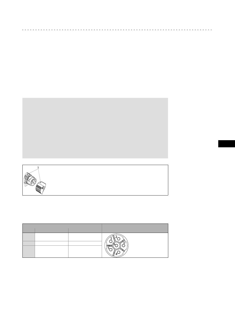
When connecting the cable socket to the motor connector, make sure that the aids to
orientation (pos. 1) are facing each other. Only then, trouble−free operation is ensured.
6.3.1
Power connections / holding brake
6−pole (external view of poles)
Pin
Standard description
Meaning
M23
1
2
BD1
BD2
Holding brake +
Holding brake −
+
PE
PE conductor
4
5
6
U
V
W
Power phase U
Power phase V
Power phase W